Chapter 4
Aerodynamic Factors
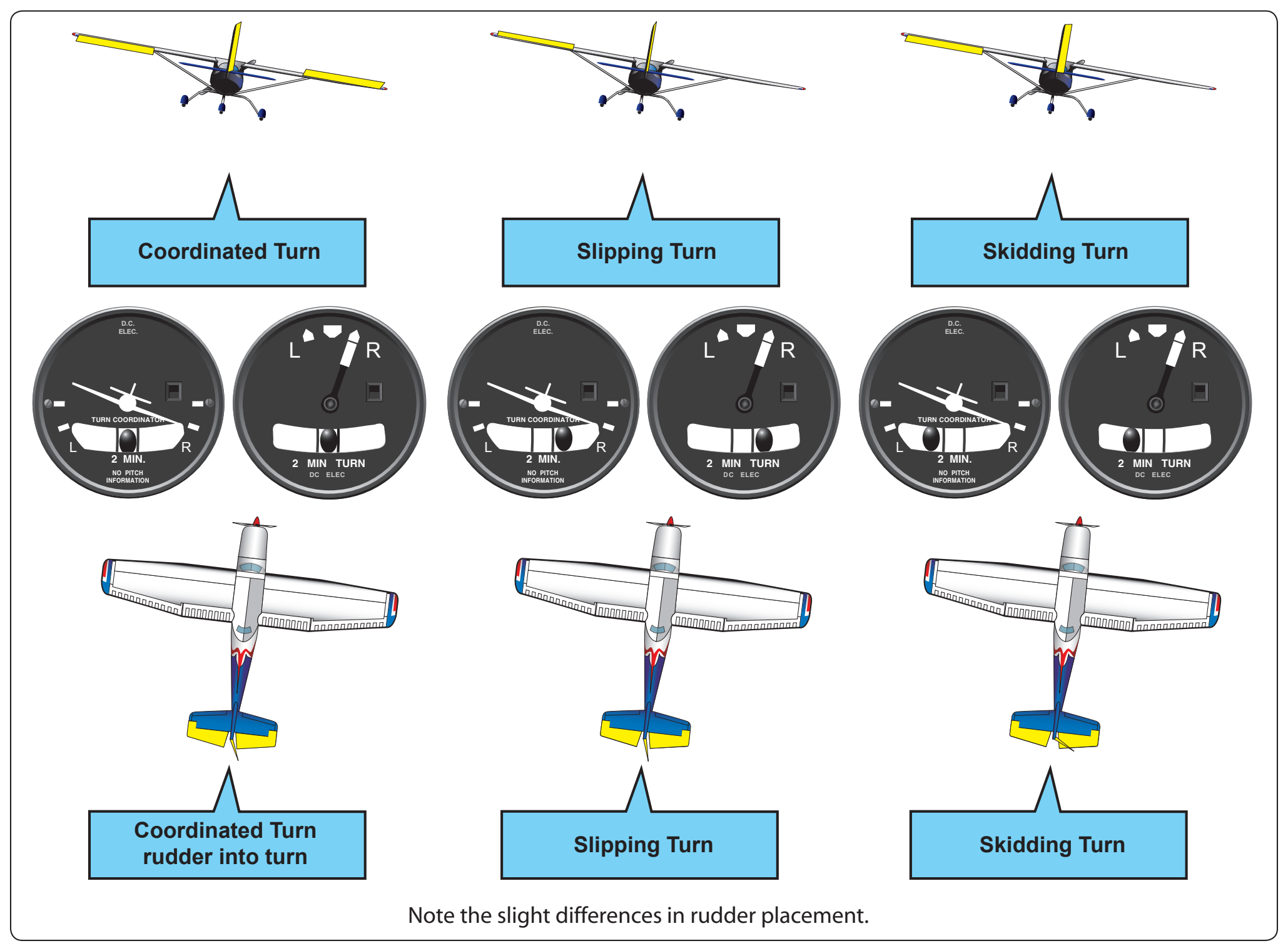
An inclinometer, located in the turn coordinator, or turn and bank indicator indicates the quality of the turn, and should be centered when the wings are banked. If the ball is off of center on the side toward the turn, the aircraft is slipping and rudder pressure should be added on that side to increase the rate of turn or the bank angle should be reduced. If the ball is off of center on the side away from the turn, the aircraft is skidding and rudder pressure toward the turn should be relaxed or the bank angle should be increased. If the aircraft is properly rigged, the ball should be in the center when the wings are level; use rudder and/or aileron trim if available.
The increase in induced drag (caused by the increase in AOA necessary to maintain altitude) results in a minor loss of airspeed if the power setting is not changed.
Load Factor
Any force applied to an aircraft to deflect its flight from a straight line produces a stress on its structure; the amount of this force is termed load factor. A load factor is the ratio of the aerodynamic force on the aircraft to the gross weight of the aircraft (e.g., lift/weight). For example, a load factor of 3 means the total load on an aircraft’s structure is three times its gross weight. When designing an aircraft, it is necessary to determine the highest load factors that can be expected in normal operation under various operational situations. These “highest” load factors are called “limit load factors.”
Aircraft are placed in various categories (i.e., normal, utility, and acrobatic) depending upon the load factors they are designed to take. For reasons of safety, the aircraft must be designed to withstand certain maximum load factors without any structural damage.
The specified load may be expected in terms of aerodynamic forces, as in turns. In level flight in undisturbed air, the wings are supporting not only the weight of the aircraft, but centrifugal force as well. As the bank steepens, the horizontal lift component increases, centrifugal force increases, and the load factor increases. If the load factor becomes so great that an increase in AOA cannot provide enough lift to support the load, the wing stalls. Since the stalling speed increases directly with the square root of the load factor, the pilot should be aware of the flight conditions during which the load factor can become critical. Steep turns at slow airspeed, structural ice accumulation, and vertical gusts in turbulent air can increase the load factor to a critical level.
Icing
One of the greatest hazards to flight is aircraft icing. The instrument pilot must be aware of the conditions conducive to aircraft icing. These conditions include the types of icing, the effects of icing on aircraft control and performance, effects of icing on aircraft systems, and the use and limitations of aircraft deice and anti-ice equipment. Coping with the hazards of icing begins with preflight planning to determine where icing may occur during a flight and ensuring the aircraft is free of ice and frost prior to takeoff. This attention to detail extends to managing deice and anti-ice systems properly during the flight, because weather conditions may change rapidly, and the pilot must be able to recognize when a change of flight plan is required.
Types of Icing
Structural Icing
Structural icing refers to the accumulation of ice on the exterior of the aircraft. Ice forms on aircraft structures and surfaces when super-cooled droplets impinge on them and freeze. Small and/or narrow objects are the best collectors of droplets and ice up most rapidly. This is why a small protuberance within sight of the pilot can be used as an “ice evidence probe.” It is generally one of the first parts of the airplane on which an appreciable amount of ice forms. An aircraft’s tailplane is a better collector than its wings, because the tailplane presents a thinner surface to the airstream.
Induction Icing
Ice in the induction system can reduce the amount of air available for combustion. The most common example of reciprocating engine induction icing is carburetor ice. Most pilots are familiar with this phenomenon, which occurs when moist air passes through a carburetor venturi and is cooled. As a result of this process, ice may form on the venturi walls and throttle plate, restricting airflow to the engine. This may occur at temperatures between 20 °F (–7 °C) and 70 °F (21 °C). The problem is remedied by applying carburetor heat, which uses the engine’s own exhaust as a heat source to melt the ice or prevent its formation. On the other hand, fuel-injected aircraft engines usually are less vulnerable to icing but still can be affected if the engine’s air source becomes blocked with ice. Manufacturers provide an alternate air source that may be selected in case the normal system malfunctions.
In turbojet aircraft, air that is drawn into the engines creates an area of reduced pressure at the inlet, which lowers the temperature below that of the surrounding air. In marginal icing conditions (i.e., conditions where icing is possible), this reduction in temperature may be sufficient to cause ice to form on the engine inlet, disrupting the airflow into the engine. Another hazard occurs when ice breaks off and is ingested into a running engine, which can cause damage to fan blades, engine compressor stall, or combustor flameout. When anti-icing systems are used, runback water also can refreeze on unprotected surfaces of the inlet and, if excessive, reduce airflow into the engine or distort the airflow pattern in such a manner as to cause compressor or fan blades to vibrate, possibly damaging the engine. Another problem in turbine engines is the icing of engine probes used to set power levels (for example, engine inlet temperature or engine pressure ratio (EPR) probes), which can lead to erroneous readings of engine instrumentation operational difficulties or total power loss.
The type of ice that forms can be classified as clear, rime, or mixed, based on the structure and appearance of the ice. The type of ice that forms varies depending on the atmospheric and flight conditions in which it forms. Significant structural icing on an aircraft can cause serious aircraft control and performance problems.
Clear Ice
A glossy, transparent ice formed by the relatively slow freezing of super cooled water is referred to as clear ice. [Figure 4-17] The terms “clear” and “glaze” have been used for essentially the same type of ice accretion. This type of ice is denser, harder, and sometimes more transparent than rime ice. With larger accretions, clear ice may form “horns.” [Figure 4-18] Temperatures close to the freezing point, large amounts of liquid water, high aircraft velocities, and large droplets are conducive to the formation of clear ice.