
Chapter 5
Flight Instruments
Introduction
Aircraft became a practical means of transportation when accurate flight instruments freed the pilot from the necessity of maintaining visual contact with the ground. Flight instruments are crucial to conducting safe flight operations and it is important that the pilot have a basic understanding of their operation. The basic flight instruments required for operation under visual flight rules (VFR) are airspeed indicator (ASI), altimeter, and magnetic direction indicator. In addition to these, operation under instrument flight rules (IFR) requires a gyroscopic rate-of-turn indicator, slip-skid indicator, sensitive altimeter adjustable for barometric pressure, clock displaying hours, minutes, and seconds with a sweep-second pointer or digital presentation, gyroscopic pitch-and-bank indicator (artificial horizon), and gyroscopic direction indicator (directional gyro or equivalent).
Aircraft that are flown in instrument meteorological conditions (IMC) are equipped with instruments that provide attitude and direction reference, as well as navigation instruments that allow precision flight from takeoff to landing with limited or no outside visual reference.
The instruments discussed in this chapter are those required by Title 14 of the Code of Federal Regulations (14 CFR) part 91, and are organized into three groups: pitot-static instruments, compass systems, and gyroscopic instruments. The chapter concludes with a discussion of how to preflight these systems for IFR flight. This chapter addresses additional avionics systems such as Electronic Flight Information Systems (EFIS), Ground Proximity Warning System (GPWS), Terrain Awareness and Warning System (TAWS), Traffic Alert and Collision Avoidance System (TCAS), Head Up Display (HUD), etc., that are increasingly being incorporated into general aviation aircraft.
Pitot/Static Systems
Pitot pressure, or impact air pressure, is sensed through an open-end tube pointed directly into the relative wind flowing around the aircraft. The pitot tube connects to the ASI or an air data computer depending on your aircraft's configuration.
Static Pressure
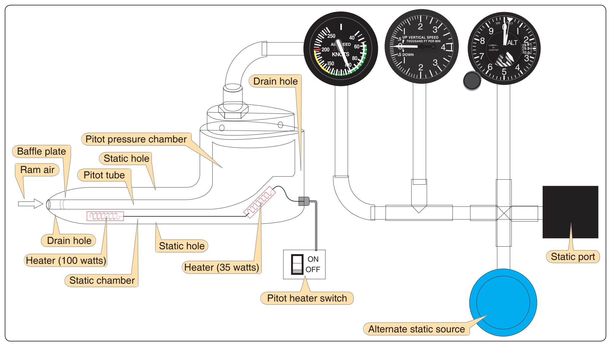
Static pressure is also used by the ASI as well as the other pitot static instruments for determining altitude and vertical speed. Static pressure may be sensed at one or more locations on an aircraft. Some may be flush mounted on the fuselage or integrated into the electrically heated pitot tube. [Figure 5-1] These ports are in locations proven by flight tests to be in undisturbed air, and they may be paired, one on either side of the aircraft. This dual location prevents lateral movement of the aircraft from giving erroneous static pressure indications. The areas around the static ports may be heated with electric heater elements to prevent ice forming over the port and blocking the entry of the static air.
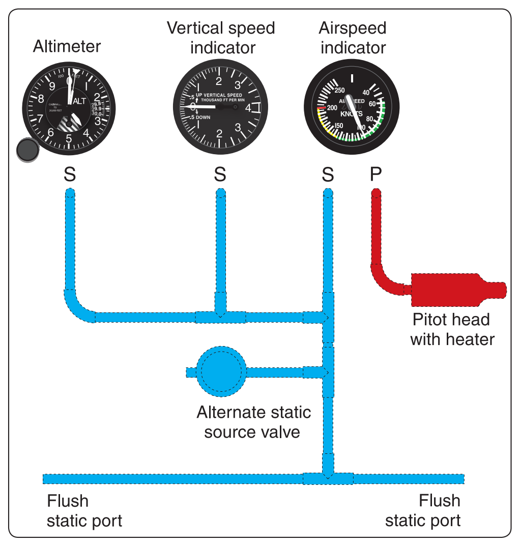
Three basic pressure-operated instruments are found in aircraft instrument panels flown under IFR. These are the ASI, sensitive altimeter, and vertical speed indicator (VSI). All three instruments receive static air pressure for operation with only the ASI receiving both pitot and static pressure. [Figure 5-2]
Blockage of the Pitot-Static System
Errors in the ASI and VSI almost always indicate a blockage of the pitot tube, the static port(s), or both. Moisture (including ice), dirt, or even insects can cause a blockage in both systems. During preflight, it is very important to make sure the pitot tube cover is removed and that static port openings are checked for blockage and damage.
Blocked Pitot System
If the pitot tube drain hole becomes obstructed, the pitot system can become partially or completely blocked. When dynamic pressure cannot enter the pitot tube opening, the ASI no longer operates. If the drain hole is open, static pressure equalizes on both sides of the diaphram in the ASI and the indicated airspeed slowly drops to zero. If the pitot tube ram pressure hole and drain hole become obstructed, the ASI operates like an altimeter as the aircraft climbs and descends. Refer to the Pilot’s Handbook of Aeronautical Knowledge (FAA-H-8083-25A) for more in depth information on blocked pitot systems along with different scenarios and how they effect the ASI.
Blocked Static System
When a static system becomes blocked but the pitot tube remains clear the ASI continues to operate but is inaccurate. When the aircraft is operated above the altitude where the static ports became blocked the airspeed indicates lower than the actual airspeed because the trapped static pressure is higher than normal for that altitude. The opposite holds true for operations at lower altitudes; a faster than actual airspeed is displayed due to the relatively low static pressure trapped in the system.
A blockage of the static system can also affect the altimeter and VSI. Trapped static pressure causes the altimeter to freeze at the altitude where the blockage occurred. In the case of the VSI, a blocked static system produces a continuous zero indication.
An alternate static source is provided in some aircraft to provide static pressure should the primary static source become blocked. The alternate static source is normally found inside of the flight deck. Due to the venturi effect of the air flowing around the fuselage, the air pressure inside the flight deck is lower than the exterior pressure.