Chapter 8
Helicopter Attitude Instrument Flying
Common Errors During Autorotations
- Uncoordinated entry due to improper pedal trim
- Poor airspeed control due to improper pitch attitude
- Poor heading control in straight-ahead autorotations
- Failure to maintain proper rotor RPM
- Failure to maintain a standard rate turn during turning autorotations
Servo Failure
Most helicopters certified for single-pilot IFR flight are required to have autopilots, which greatly reduces pilot workload. If an autopilot servo fails, however, resume manual control of the helicopter. The amount of workload increase depends on which servo fails. If a cyclic servo fails, a pilot may want to land immediately because the workload increases tremendously. If an antitorque or collective servo fails, continuing to the next suitable landing site might be possible.
Instrument Takeoff
The procedures and techniques described here should be modified as necessary to conform to those set forth in the operating instructions for the particular helicopter being flown. During training, instrument takeoffs should not be attempted except when receiving instruction from an appropriately certificated, proficient flight instructor pilot.
Adjust the miniature aircraft in the attitude indicator, as appropriate, for the aircraft being flown. After the helicopter is aligned with the runway or takeoff pad, to prevent forward movement of a helicopter equipped with a wheel-type landing gear, set the parking brakes or apply the toe brakes. If the parking brake is used, it must be unlocked after the takeoff has been completed. Apply sufficient friction to the collective pitch control to minimize overcontrolling and to prevent creeping. Excessive friction should be avoided since it limits collective pitch movement.
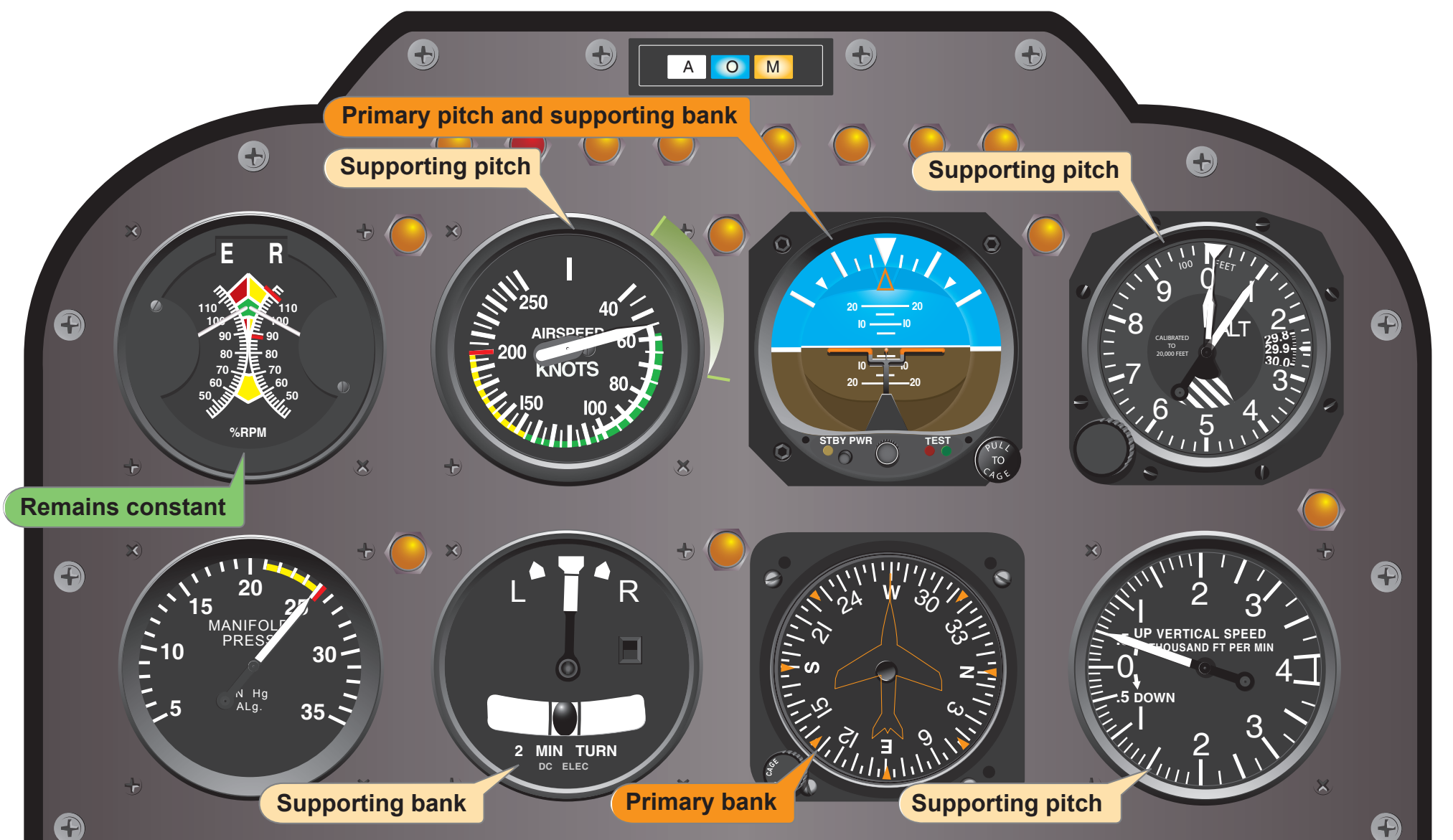
After checking all instruments for proper indications, start the takeoff by applying collective pitch and a predetermined power setting. Add power smoothly and steadily to gain airspeed and altitude simultaneously and to prevent settling to the ground. As power is applied and the helicopter becomes airborne, use the antitorque pedals initially to maintain the desired heading. At the same time, apply forward cyclic to begin accelerating to climbing airspeed. During the initial acceleration, the pitch attitude of the helicopter, as read on the attitude indicator, should be one- to two-bar widths low. The primary and supporting instruments after becoming airborne are illustrated in Figure 8-16. As the airspeed increases to the appropriate climb airspeed, adjust pitch gradually to climb attitude. As climb airspeed is reached, reduce power to the climb power setting and transition to a fully coordinated straight climb.
During the initial climb out, minor heading corrections should be made with pedals only until sufficient airspeed is attained to transition to fully coordinated flight. Throughout the instrument takeoff, instrument cross-check and interpretations must be rapid and accurate and aircraft control positive and smooth.
Common Errors During Instrument Takeoffs
- Failure to maintain heading
- Overcontrolling pedals
- Failure to use required power
- Failure to adjust pitch attitude as climbing airspeed is reached
Changing Technology
Advances in technology have brought about changes in the instrumentation found in all types of aircraft, including helicopters. Electronic displays commonly referred to as “glass cockpits” are becoming more common. Primary flight displays (PFDs) and multi-function displays (MFDs) are changing not only what information is available to a pilot but also how that information is displayed.
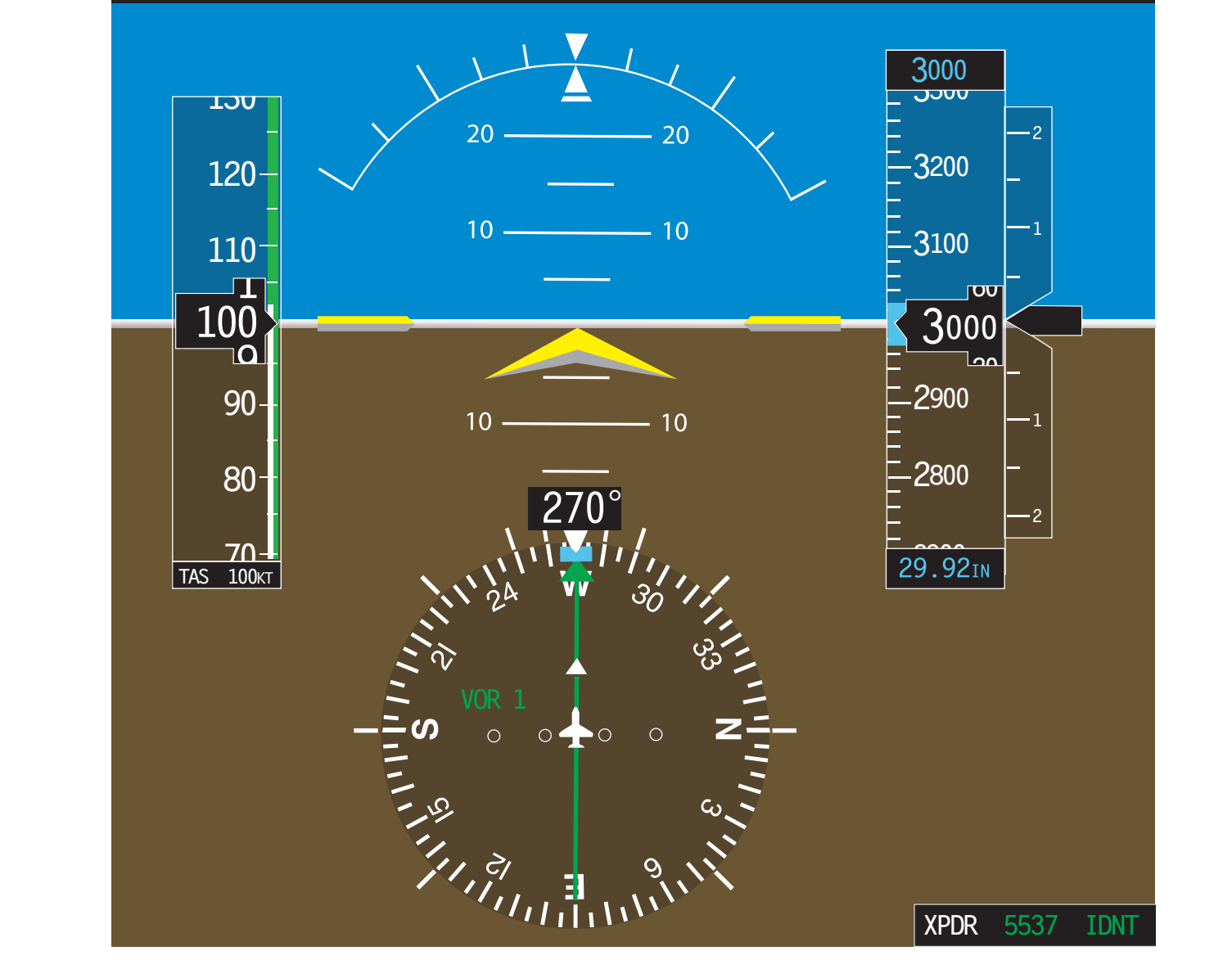
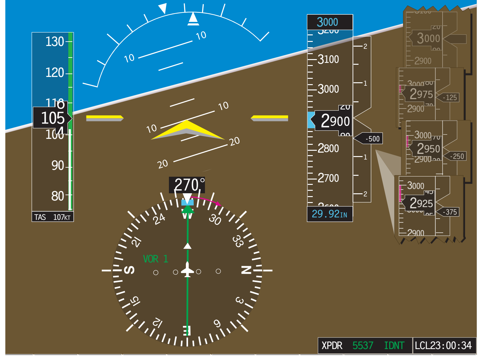
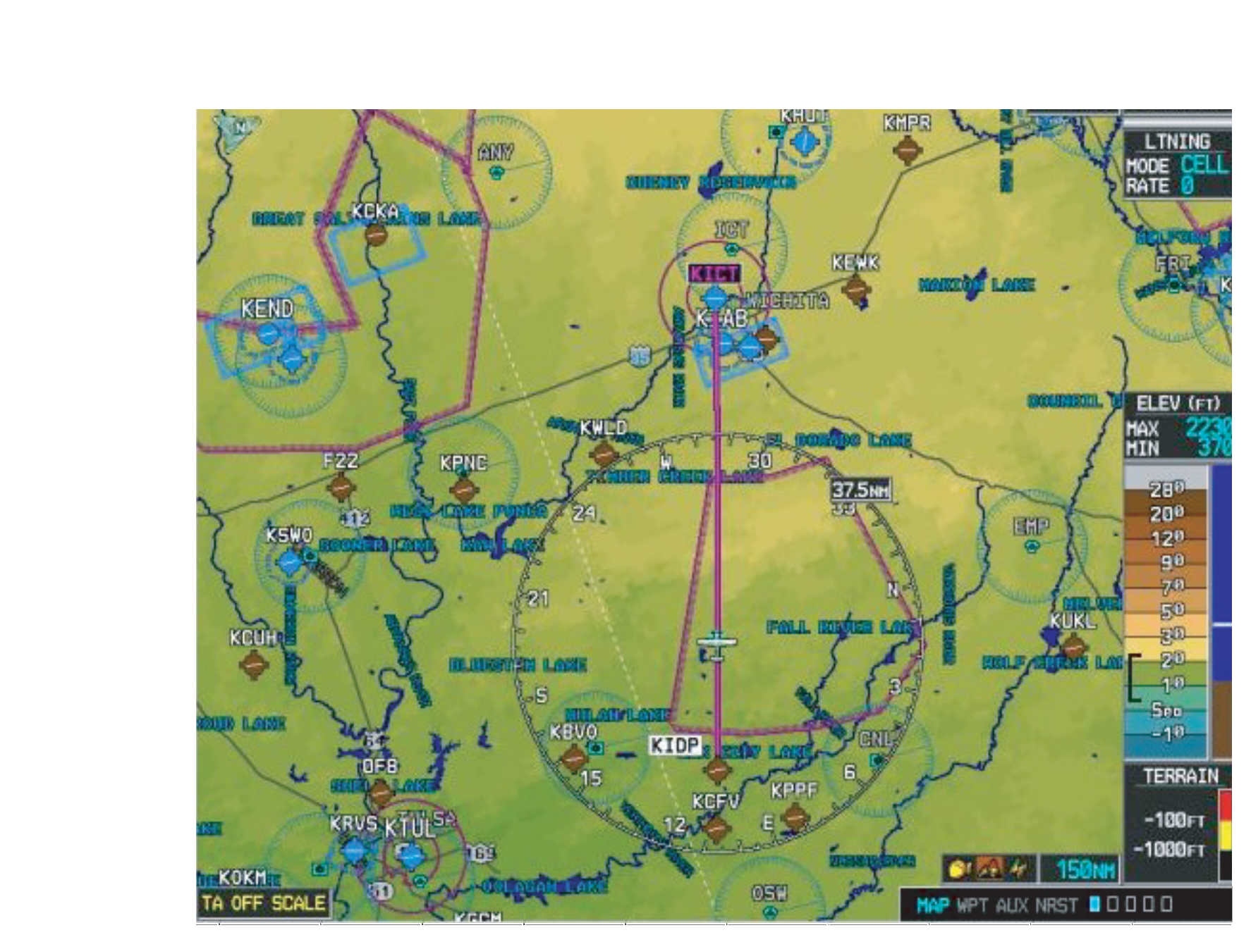
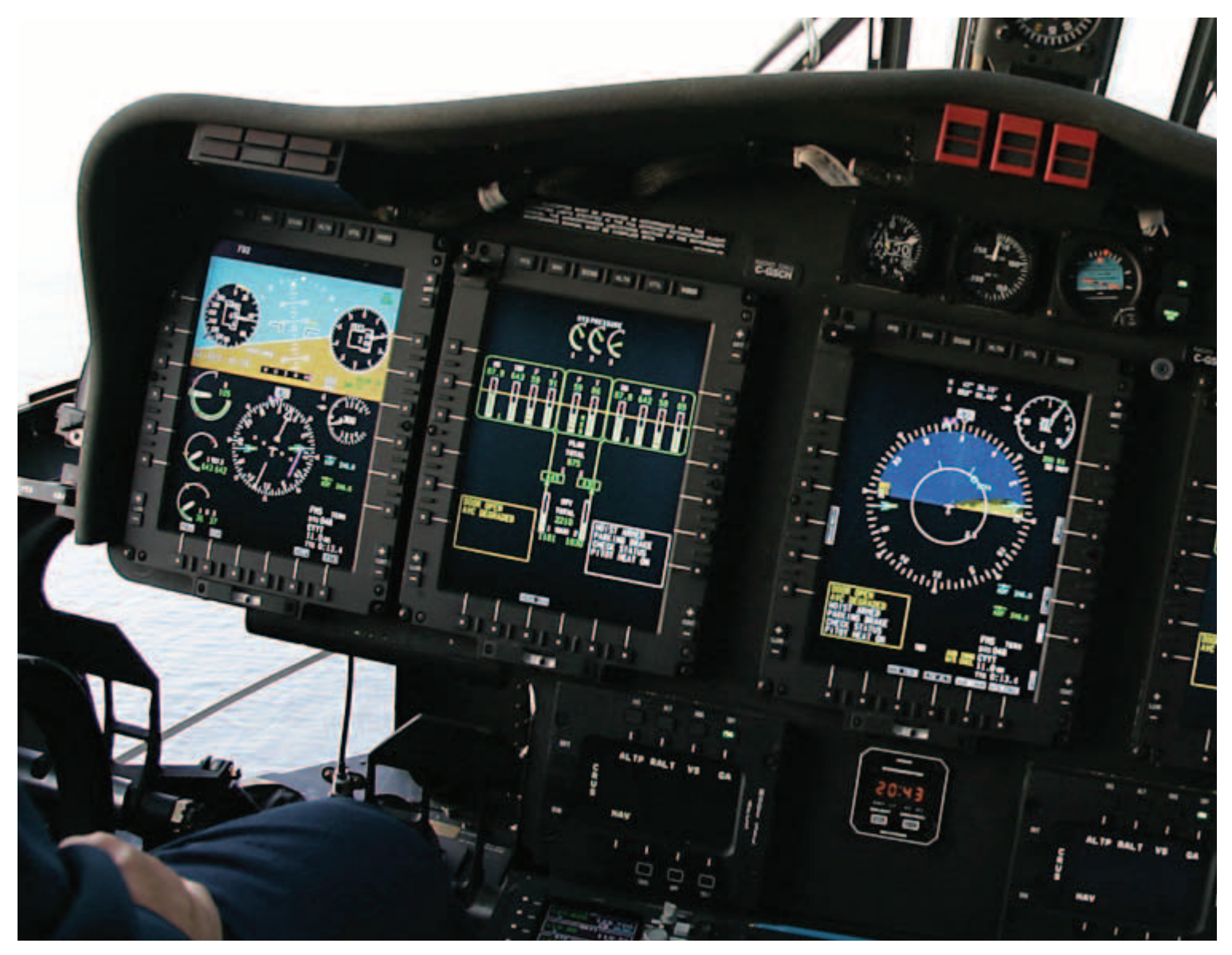
Illustrations of technological advancements in instrumentation are described as follows. In Figure 8-17, a typical PFD depicts an aircraft flying straight-and-level at 3,000 feet and 100 knots. Figure 8-18 illustrates a nose-low pitch attitude in a right turn. MFDs can be configured to provide navigation information, such as the moving map in Figure 8-19 or information pertaining to aircraft systems as in Figure 8-20.