
Chapter 9
Navigation Systems
The SDF must provide signals sufficient to allow satisfactory operation of a typical aircraft installation within a sector which extends from the center of the SDF antenna system to distances of 18 NM covering a sector 10° either side of centerline up to an angle 7° above the horizontal. The angle of convergence of the final approach course and the extended runway centerline must not exceed 30°. Pilots should note this angle since the approach course originates at the antenna site, and an approach continued beyond the runway threshold would lead the aircraft to the SDF offset position rather than along the runway centerline.
The course width of the SDF signal emitted from the transmitter is fixed at either 6° or 12°, as necessary, to provide maximum flyability and optimum approach course quality. A three-letter identifier is transmitted in code on the SDF frequency; there is no letter “I” (two dots) transmitted before the station identifier, as there is with the LOC. For example, the identifier for Lebanon, Missouri, SDF is LBO.
Localizer Type Directional Aid (LDA)
The localizer type directional aid (LDA) is of comparable utility and accuracy to a localizer but is not part of a complete ILS. The LDA course width is between 3° and 6° and thus provides a more precise approach course than an SDF installation. Some LDAs are equipped with a GS. The LDA course is not aligned with the runway, but straight-in minimums may be published where the angle between the runway centerline and the LDA course does not exceed 30°. If this angle exceeds 30°, only circling minimums are published. The identifier is three letters preceded by “I” transmitted in code on the LDA frequency. For example, the identifier for Van Nuys, California, LDA is I-BUR.
Microwave Landing System (MLS)
The microwave landing system (MLS) provides precision navigation guidance for exact alignment and descent of aircraft on approach to a runway. It provides azimuth, elevation, and distance. Both lateral and vertical guidance may be displayed on conventional course deviation indicators or incorporated into multipurpose flight deck displays. Range information can be displayed by conventional DME indicators and also incorporated into multipurpose displays. [Figure 9-40]
The system may be divided into five functions, which are approach azimuth, back azimuth, approach elevation, range; and data communications. The standard configuration of MLS ground equipment includes an azimuth station to perform functions as indicated above. In addition to providing azimuth navigation guidance, the station transmits basic data, which consists of information associated directly with the operation of the landing system, as well as advisory data on the performance of the ground equipment.
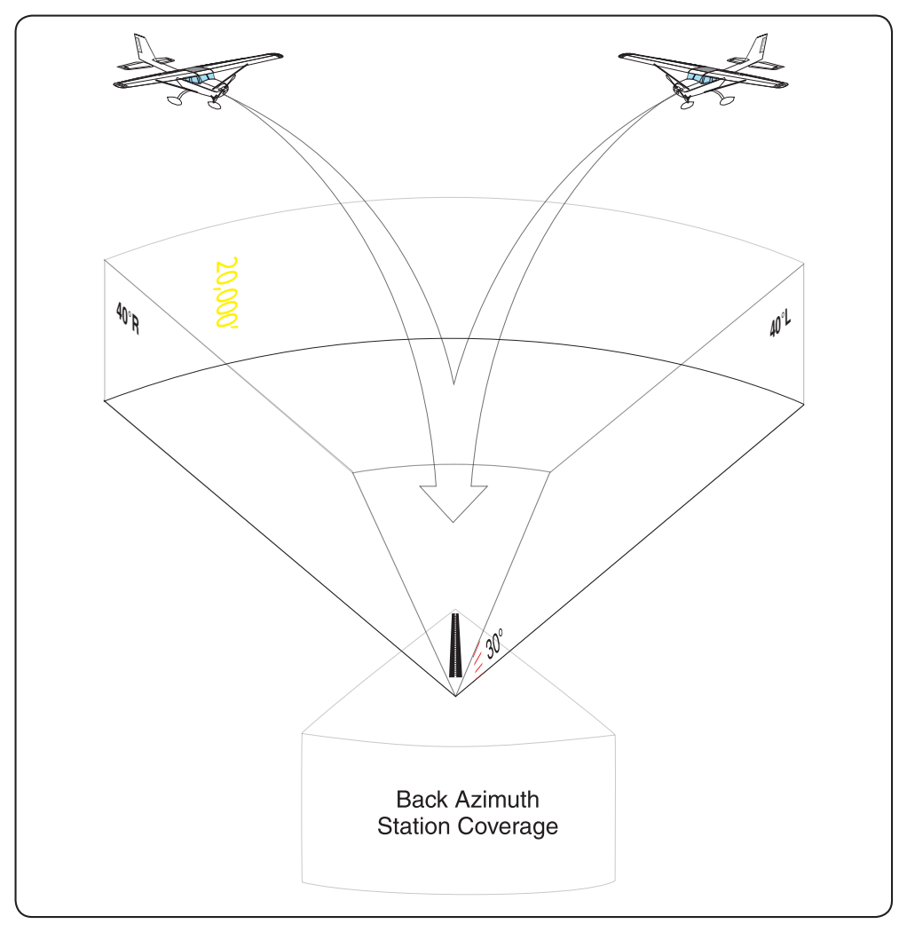
Approach Azimuth Guidance
The azimuth station transmits MLS angle and data on one of 200 channels within the frequency range of 5031 to 5091 MHz. The equipment is normally located about 1,000 feet beyond the stop end of the runway, but there is considerable flexibility in selecting sites. For example, for heliport operations the azimuth transmitter can be collocated with the elevation transmitter. The azimuth coverage extends laterally at least 40° on either side of the runway centerline in a standard configuration, in elevation up to an angle of 15° and to at least 20,000 feet, and in range to at least 20 NM.
MLS requires separate airborne equipment to receive and process the signals from what is normally installed in general aviation aircraft today. It has data communications capability, and can provide audible information about the condition of the transmitting system and other pertinent data such as weather, runway status, etc. The MLS transmits an audible identifier consisting of four letters beginning with the letter M, in Morse code at a rate of at least six per minute. The MLS system monitors itself and transmits ground-to-air data messages about the system’s operational condition. During periods of routine or emergency maintenance, the coded identification is missing from the transmissions. At this time there are only a few systems installed.
Required Navigation Performance
RNP is a navigation system that provides a specified level of accuracy defined by a lateral area of confined airspace in which an RNP-certified aircraft operates. The continuing growth of aviation places increasing demands on airspace capacity and emphasizes the need for the best use of the available airspace. These factors, along with the accuracy of modern aviation navigation systems and the requirement for increased operational efficiency in terms of direct routings and track-keeping accuracy, have resulted in the concept of required navigation performance—a statement of the navigation performance accuracy necessary for operation within a defined airspace. RNP can include both performance and functional requirements and is indicated by the RNP type. These standards are intended for designers, manufacturers, and installers of avionics equipment, as well as service providers and users of these systems for global operations. The minimum aviation system performance specification (MASPS) provides guidance for the development of airspace and operational procedures needed to obtain the benefits of improved navigation capability. [Figure 9-41]
The RNP type defines the total system error (TSE) that is allowed in lateral and longitudinal dimensions within a particular airspace. The TSE, which takes account of navigation system errors (NSE), computation errors, display errors and flight technical errors (FTE), must not exceed the specified RNP value for 95 percent of the flight time on any part of any single flight. RNP combines the accuracy standards laid out in the ICAO Manual (Doc 9613) with specific accuracy requirements, as well as functional and performance standards, for the RNAV system to realize a system that can meet future air traffic management requirements. The functional criteria for RNP address the need for the flightpaths of participating aircraft to be both predictable and repeatable to the declared levels of accuracy. More information on RNP is contained in subsequent chapters.
The term RNP is also applied as a descriptor for airspace, routes, and procedures (including departures, arrivals, and IAPs). The descriptor can apply to a unique approach procedure or to a large region of airspace. RNP applies to navigation performance within a designated airspace and includes the capability of both the available infrastructure (navigation aids) and the aircraft.
RNP type is used to specify navigation requirements for the airspace. The following are ICAO RNP Types: RNP-1.0, RNP-4.0, RNP-5.0, and RNP-10.0. The required performance is obtained through a combination of aircraft capability and the level of service provided by the corresponding navigation infrastructure. From a broad perspective: Aircraft Capability + Level of Service = Access
In this context, aircraft capability refers to the airworthiness certification and operational approval elements (including avionics, maintenance, database, human factors, pilot procedures, training, and other issues). The level of service element refers to the NAS infrastructure, including published routes, signal-in-space performance and availability, and air traffic management. When considered collectively, these elements result in providing access. Access provides the desired benefit (airspace, procedures, routes of flight, etc.).
RNP levels are actual distances from the centerline of the flightpath, which must be maintained for aircraft and obstacle separation. Although additional FAA-recognized RNP levels may be used for specific operations, the United States currently supports three standard RNP levels:
- RNP 0.3 – Approach
- RNP 1.0 – Departure, Terminal
- RNP 2.0 – En route
RNP 0.3 represents a distance of 0.3 NM either side of a specified flightpath centerline. The specific performance that is required on the final approach segment of an instrument approach is an example of this RNP level. At the present time, a 0.3 RNP level is the lowest level used in normal RNAV operations. Specific airlines, using special procedures, are approved to use RNP levels lower than RNP 0.3, but those levels are used only in accordance with their approved operations specifications (OpsSpecs). For aircraft equipment to qualify for a specific RNP type, it must maintain navigational accuracy at least 95 percent of the total flight time.