
Chapter 9
Navigation Systems
Flight Management Systems (FMS)
A flight management system (FMS) is not a navigation system in itself. Rather, it is a system that automates the tasks of managing the onboard navigation systems. FMS may perform other onboard management tasks, but this discussion is limited to its navigation function.
FMS is an interface between flight crews and flightdeck systems. FMS can be thought of as a computer with a large database of airport and NAVAID locations and associated data, aircraft performance data, airways, intersections, DPs, and STARs. FMS also has the ability to accept and store numerous user-defined WPs, flight routes consisting of departures, WPs, arrivals, approaches, alternates, etc. FMS can quickly define a desired route from the aircraft’s current position to any point in the world, perform flight plan computations, and display the total picture of the flight route to the crew.
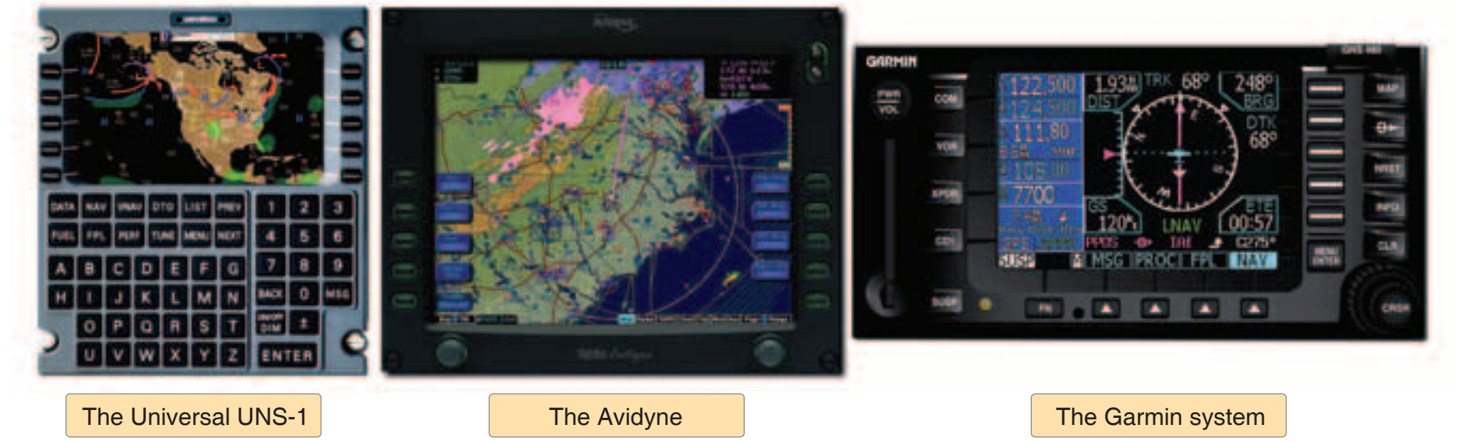
FMS also has the capability of controlling (selecting) VOR, DME, and LOC NAVAIDs, and then receiving navigational data from them. INS, LORAN, and GPS navigational data may also be accepted by the FMS computer. The FMS may act as the input/output device for the onboard navigation systems, so that it becomes the “go-between” for the crew and the navigation systems.
Function of FMS
At startup, the crew programs the aircraft location, departure runway, DP (if applicable), WPs defining the route, approach procedure, approach to be used, and routing to alternate. This may be entered manually, be in the form of a stored flight plan, or be a flight plan developed in another computer and transferred by disk or electronically to the FMS computer. The crew enters this basic information in the control/display unit (CDU). [Figure 9-42]
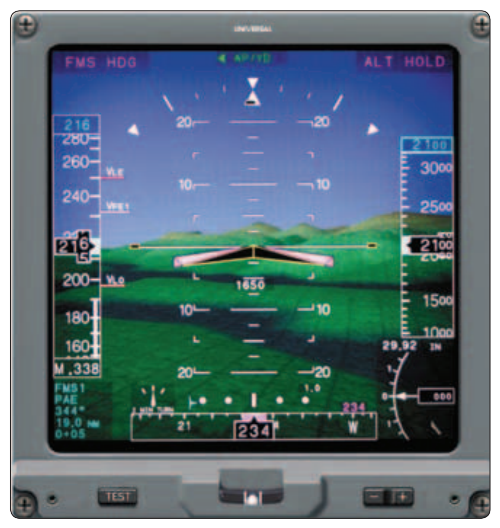
Once airborne, the FMS computer channels the appropriate NAVAIDs and takes radial/distance information or channels two NAVAIDs, taking the more accurate distance information. FMS then indicates position, track, desired heading, groundspeed, and position relative to desired track. Position information from the FMS updates the INS. In more sophisticated aircraft, the FMS provides inputs to the HSI, RMI, glass flight deck navigation displays, head-up display (HUD), autopilot, and autothrottle systems.
Head-Up Display (HUD)
The HUD is a display system that provides a projection of navigation and air data (airspeed in relation to approach reference speed, altitude, left/right and up/down GS) on a transparent screen between the pilot and the windshield. Other information may be displayed, including a runway target in relation to the nose of the aircraft. This allows the pilot to see the information necessary to make the approach while also being able to see out the windshield, which diminishes the need to shift between looking at the panel to looking outside. Virtually any information desired can be displayed on the HUD if it is available in the aircraft’s flight computer and if the display is user definable. [Figure 9-43]
Radar Navigation (Ground-Based)
Radar works by transmitting a pulse of RF energy in a specific direction. The return of the echo or bounce of that pulse from a target is precisely timed. From this, the distance traveled by the pulse and its echo is determined and displayed on a radar screen in such a manner that the distance and bearing to this target can be instantly determined. The radar transmitter must be capable of delivering extremely high power levels toward the airspace under surveillance, and the associated radar receiver must be able to detect extremely small signal levels of the returning echoes.
The radar display system provides the controller with a map-like presentation upon which appear all the radar echoes of aircraft within detection range of the radar facility. By means of electronically-generated range marks and azimuth-indicating devices, the controller can locate each radar target with respect to the radar facility, or can locate one radar target with respect to another.
Another device, a video-mapping unit, generates an actual airway or airport map and presents it on the radar display equipment. Using the video-mapping feature, the air traffic controller not only can view the aircraft targets, but can see these targets in relation to runways, navigation aids, and hazardous ground obstructions in the area. Therefore, radar becomes a NAVAID, as well as the most significant means of traffic separation.
In a display presenting perhaps a dozen or more targets, a primary surveillance radar system cannot identify one specific radar target, and it may have difficulty “seeing” a small target at considerable distance—especially if there is a rain shower or thunderstorm between the radar site and the aircraft. This problem is solved with the Air Traffic Control Radar Beacon System (ATCRBS), sometimes called secondary surveillance radar (SSR), which utilizes a transponder in the aircraft. The ground equipment is an interrogating unit, in which the beacon antenna is mounted so it rotates with the surveillance antenna. The interrogating unit transmits a coded pulse sequence that actuates the aircraft transponder. The transponder answers the coded sequence by transmitting a preselected coded sequence back to the ground equipment, providing a strong return signal and positive aircraft identification, as well as other special data such as aircraft altitude.
Functions of Radar Navigation
The radar systems used by ATC are air route surveillance radar (ARSR), airport surveillance radar (ASR), and precision approach radar (PAR) and airport surface detection equipment (ASDE). Surveillance radars scan through 360° of azimuth and present target information on a radar display located in a tower or center. This information is used independently or in conjunction with other navigational aids in the control of air traffic.
ARSR is a long-range radar system designed primarily to cover large areas and provide a display of aircraft while en route between terminal areas. The ARSR enables air route traffic control center (ARTCC) controllers to provide radar service when the aircraft are within the ARSR coverage. In some instances, ARSR may enable ARTCC to provide terminal radar services similar to but usually more limited than those provided by a radar approach control.