Chapter 4
Approaches
On rare occasions, ATC may clear the aircraft for an approach at the airport without specifying the approach procedure by name or by a specific approach (e.g., “cleared RNAV Runway 34 approach”) without specifying a particular IAF. In either case, the pilot should proceed direct to the IAF or to the IF/IAF associated with the sector that the aircraft will enter the TAA and join the approach course from that point and if required by that sector (i.e., sector is not labeled “NoPT), complete the HILO course reversal.
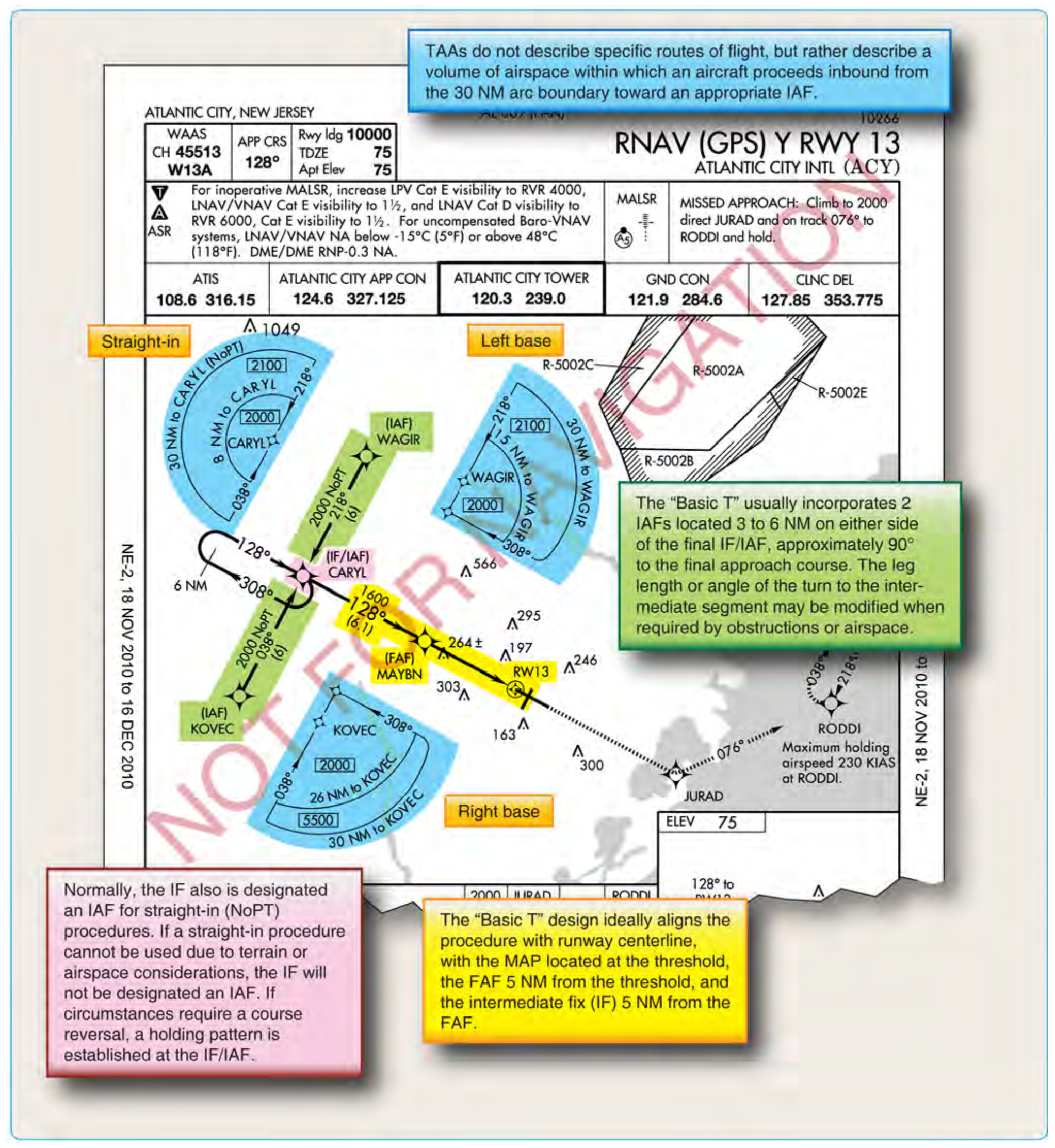
Altitudes published within the TAA replace the MSA altitude. However, unlike MSA altitudes the TAA altitudes are operationally usable altitudes. These altitudes provide at least 1,000 feet of obstacle clearance, and more in mountainous areas. It is important that the pilot knows which area of the TAA that the aircraft will enter in order to comply with the minimum altitude requirements. The pilot can determine which area of the TAA the aircraft will enter by determining the magnetic bearing of the aircraft TO the fix labeled IF/IAF. The bearing should then be compared to the published lateral boundary bearings that define the TAA areas. Do not use magnetic bearing to the right-base or left-base IAFs to determine position.
An ATC clearance direct to an IAF or to the IF/IAF without an approach clearance does not authorize a pilot to descend to a lower TAA altitude. If a pilot desires a lower altitude without an approach clearance, request the lower TAA altitude from ATC. Pilots not sure of the clearance should confirm their clearance with ATC or request a specific clearance. Pilots entering the TAA with two−way radio communications failure (14 CFR § 91.185, IFR Operations: Two−way Radio Communications Failure), must maintain the highest altitude prescribed by 14 CFR § 91.185(c)(2) until arriving at the appropriate IAF.
Once cleared for the approach, pilots may descend in the TAA sector to the minimum altitude depicted within the defined area/subdivision, unless instructed otherwise by air traffic control. Pilots should plan their descent within the TAA to permit a normal descent from the IF/IAF to the FAF.
U.S. Government charts depict TAAs using icons located in the plan view outside the depiction of the actual approach procedure. Use of icons is necessary to avoid obscuring any portion of the “T” procedure (altitudes, courses, minimum altitudes, etc.). The icon for each TAA area will be located and oriented on the plan view with respect to the direction of arrival to the approach procedure, and will show all TAA minimum altitudes and sector/radius subdivisions. The IAF for each area of the TAA is included on the icon where it appears on the approach to help the pilot orient the icon to the approach procedure. The IAF name and the distance of the TAA area boundary from the IAF are included on the outside arc of the TAA area icon.
TAAs may be modified from the standard size and shape to accommodate operational or ATC requirements. Some areas may be eliminated, while the other areas are expanded. The “T” design may be modified by the procedure designers where required by terrain or ATC considerations. For instance, the “T” design may appear more like a regularly or irregularly shaped “Y,” an upside down “L,” or an “I.”
When an airway does not cross the lateral TAA boundaries, a feeder route will be established from an airway fix or NAVAID to the TAA boundary to provide a transition from the en route structure to the appropriate IAF. Each feeder route will terminate at the TAA boundary and will be aligned along a path pointing to the associated IAF. Pilots should descend to the TAA altitude after crossing the TAA boundary and cleared for the approach by ATC.
Each waypoint on the “T” is assigned a pronounceable 5− letter name, except the missed approach waypoint. These names are used for ATC communications, RNAV databases, and aeronautical navigation products. The missed approach waypoint is assigned a pronounceable name when it is not located at the runway threshold.
RNAV Approach Types
RNAV encompasses a variety of underlying navigation systems and, therefore, approach criteria. This results in different sets of criteria for the final approach segment of various RNAV approaches. RNAV instrument approach criteria address the following procedures:
- GPS overlay of pre-existing nonprecision approaches.
- VOR/DME based RNAV approaches.
- Stand-alone RNAV (GPS) approaches.
- RNAV (GPS) approaches with vertical guidance (APV).
- RNAV (GPS) precision approaches (WAAS and LAAS).
GPS Overlay of Nonprecision Approach
The original GPS approach procedures provided authorization to fly non-precision approaches based on conventional, ground-based NAVAIDs. Many of these approaches have been converted to stand-alone approaches, and the few that remain are identified by the name of the procedure and “or GPS.” These GPS non-precision approaches are predicated upon the design criteria of the ground-based NAVAID used as the basis of the approach. As such, they do not adhere to the RNAV design criteria for stand-alone GPS approaches, and are not considered part of the RNAV (GPS) approach classification for determining design criteria. [Figure 4-38]
GPS Stand-Alone/RNAV (GPS) Approach
The number of GPS stand-alone approaches continues to decrease as they are replaced by RNAV approaches. RNAV (GPS) approaches are named so that airborne navigation databases can use either GPS or RNAV as the title of the approach. This is required for non-GPS approach systems, such as VOR/DME based RNAV systems. In the past, these approaches were often referred to as "stand-alone GPS" approaches. They are considered non-precision approaches, offering only LNAV and circling minimums. Precision minimums are not authorized, although LNAV/VNAV minimums may be published and used as long as the on-board system is capable of providing approach approved VNAV. The RNAV (GPS) Runway 14 approach for Lincoln, Nebraska, incorporates only LNAV and circling minimums. [Figure 4-39]
For a non-vertically guided straight-in RNAV (GPS) approach, the final approach course must be aligned within 15° of the extended runway centerline. The final approach segment should not exceed 10 NM, and when it exceeds 6 NM, a stepdown fix is typically incorporated. A minimum of 250 feet obstacle clearance is also incorporated into the final approach segment for straight-in approaches, and a maximum 400-ft/NM descent gradient is permitted. The approach design criteria are different for approaches that use vertical guidance provided by a Baro-VNAV system. Because the Baro-VNAV guidance is advisory and not primary, Baro-VNAV approaches are not authorized in areas of hazardous terrain, nor are they authorized when a remote altimeter setting is required. Due to the inherent problems associated with barometric readings and cold temperatures, these procedures are also temperature limited. Additional approach design criteria for RNAV Approach Construction Criteria can be found in the appropriate FAA Order 8260-series orders.