
Chapter 4
Approaches
Information about radar approaches is published in tabular form in the front of the TPP booklet. PAR, ASR, and circling approach information including runway, DA, DH, or MDA, height above airport (HAA), HAT, ceiling, and visibility criteria are outlined and listed by specific airport.
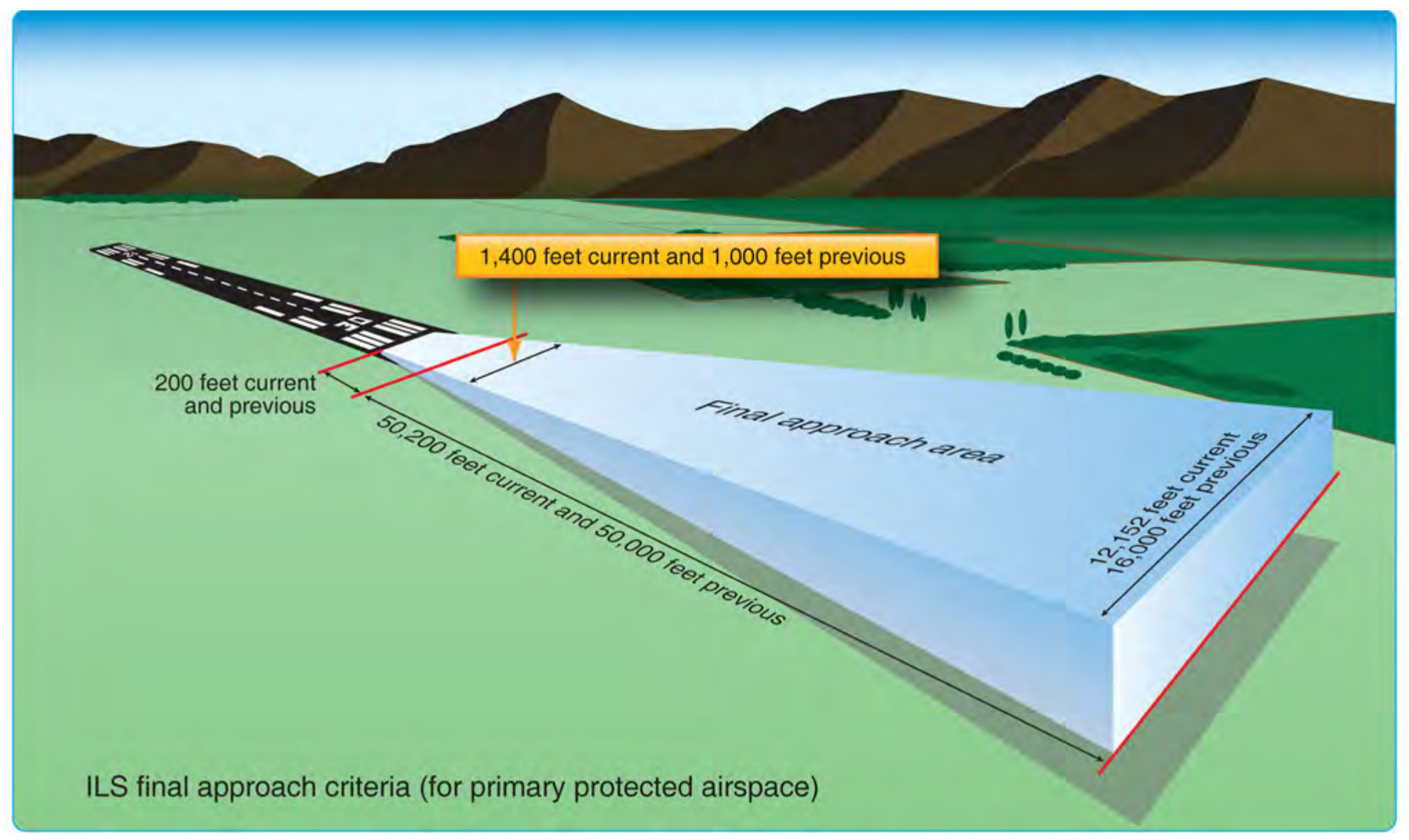
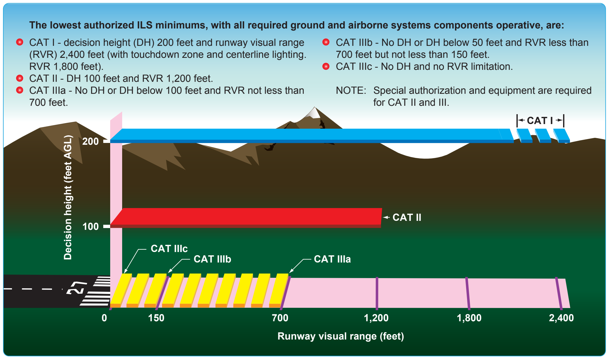
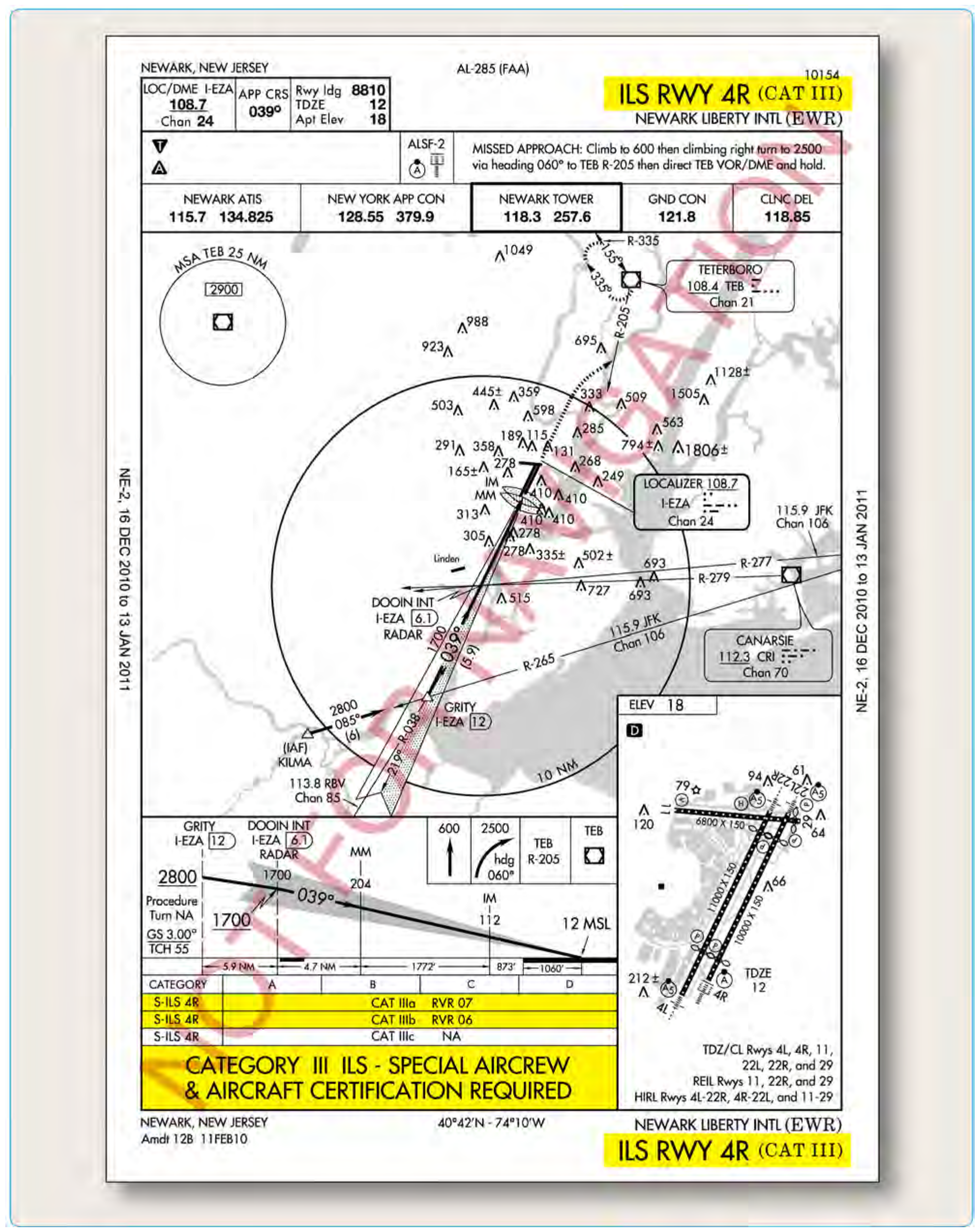
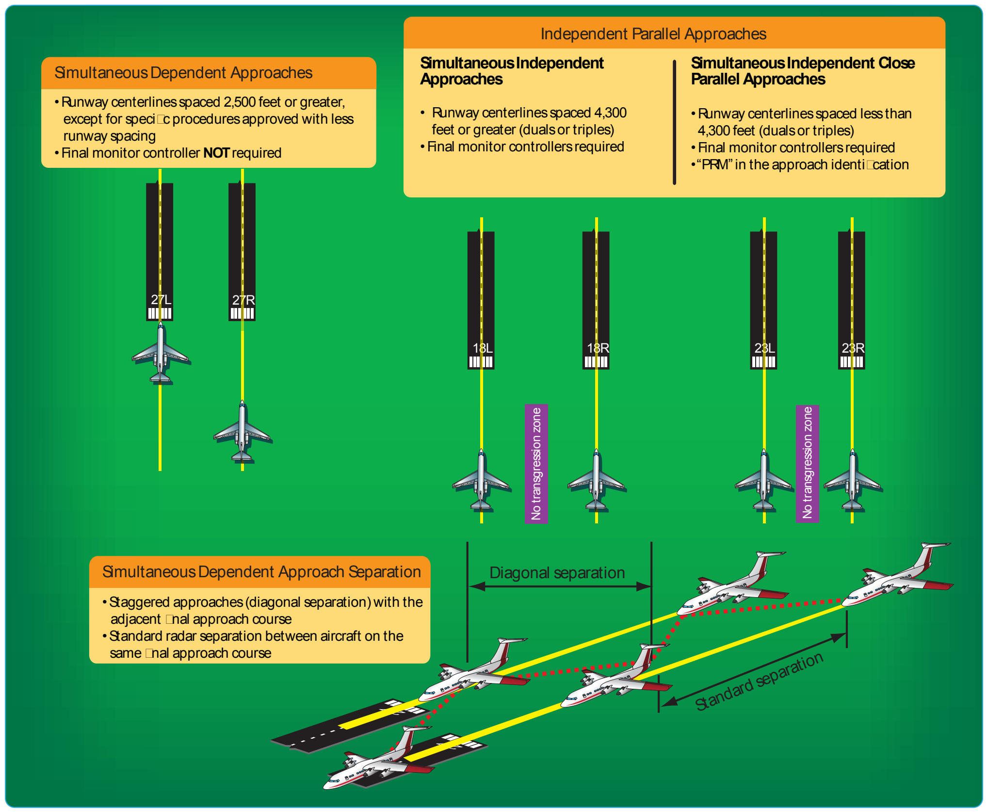
Regardless of the type of radar approach in use, ATC monitors aircraft position and issues specific heading and altitude information throughout the entire approach. Particularly, lost communications procedures should be briefed prior to execution to ensure pilots have a comprehensive understanding of ATC expectations if radio communication were lost. ATC also provides additional information concerning weather and missed approach instructions when beginning a radar approach. [Figure 4-56]
Precision Approach Radar (PAR)
PAR provides both vertical and lateral guidance, as well as range, much like an ILS, making it the most precise radar approach available. The radar approach, however, is not able to provide visual approach indications in the flight deck. This requires the flight crew to listen and comply with controller instructions. PAR approaches are rare, with most of the approaches used in a military setting; any opportunity to practice this type of approach is beneficial to any flight crew.
The final approach course of a PAR approach is normally aligned with the runway centerline, and the associated glideslope is typically no less than 2.5° and no more than 3°. Obstacle clearance for the final approach area is based on the particular established glideslope angle and the exact formula is outlined in FAA Order 8260.3. [Figure 4-57]
Airport Surveillance Radar (ASR)
ASR approaches are typically only approved when necessitated for an ATC operational requirement or in an unusual or emergency situation. This type of radar only provides heading and range information, although the controller can advise the pilot of the altitude where the aircraft should be based on the distance from the runway. An ASR approach procedure can be established at any radar facility that has an antenna within 20 NM of the airport and meets the equipment requirements outlined in FAA Order 8200.1, U.S. Standard Flight Inspection Manual. ASR approaches are not authorized for use when Center Radar ARTS processing (CENRAP) procedures are in use due to diminished radar capability.
The final approach course for an ASR approach is aligned with the runway centerline for straight-in approaches and aligned with the center of the airport for circling approaches. Within the final approach area, the pilot is also guaranteed a minimum of 250 feet obstacle clearance. ASR descent gradients are designed to be relatively flat, with an optimal gradient of 150 feet per mile and never exceeding 300 feet per mile.
Localizer Approaches
As an approach system, the localizer is an extremely flexible approach aid that, due to its inherent design, provides many applications for a variety of needs in instrument flying. An ILS glideslope installation may be impossible due to surrounding terrain. The localizer is able to provide four separate types of non-precision approaches from one approach system:
- Localizer approach
- Localizer/DME approach
- Localizer back course approach
- Localizer-type directional aid (LDA)
Localizer and Localizer DME
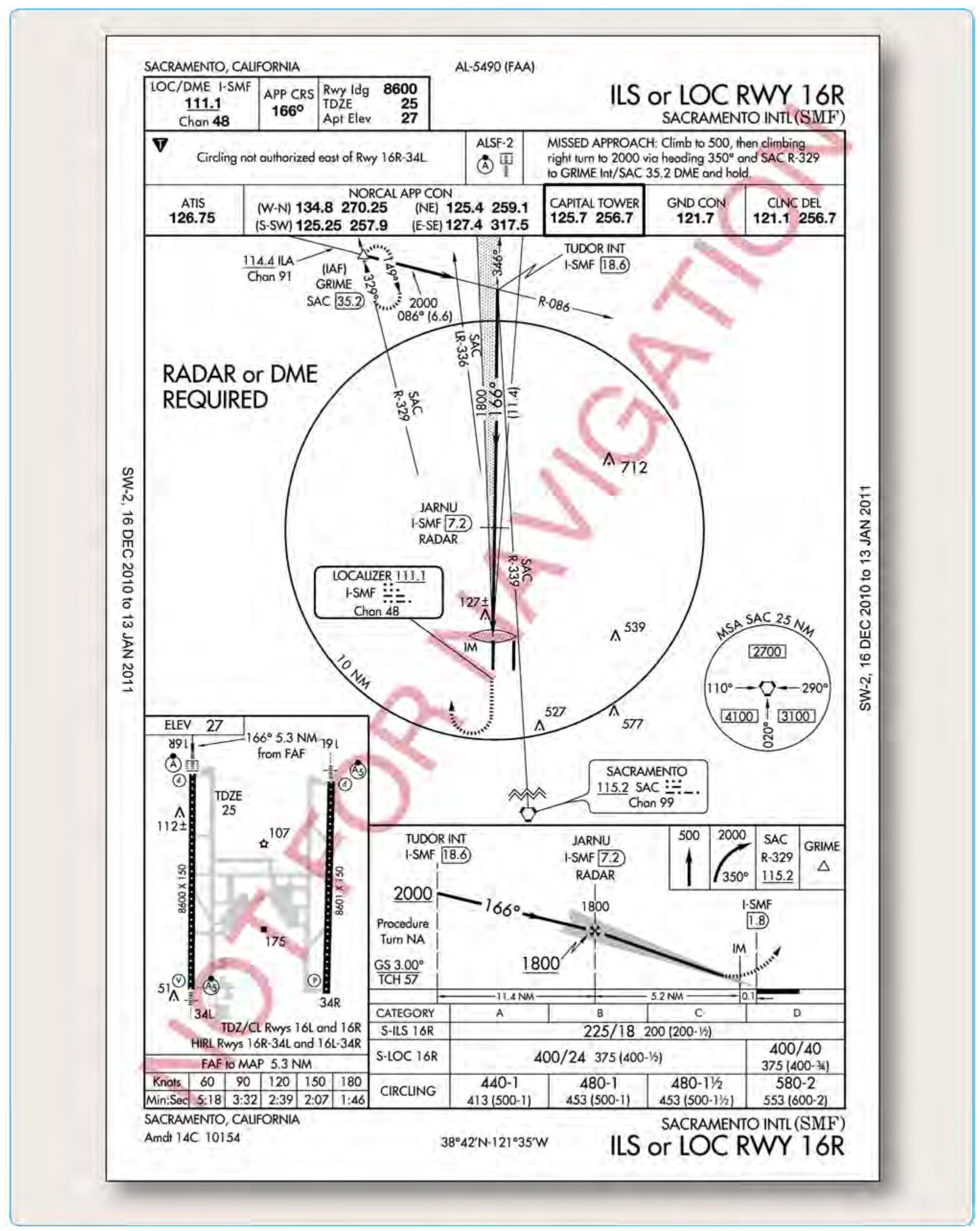
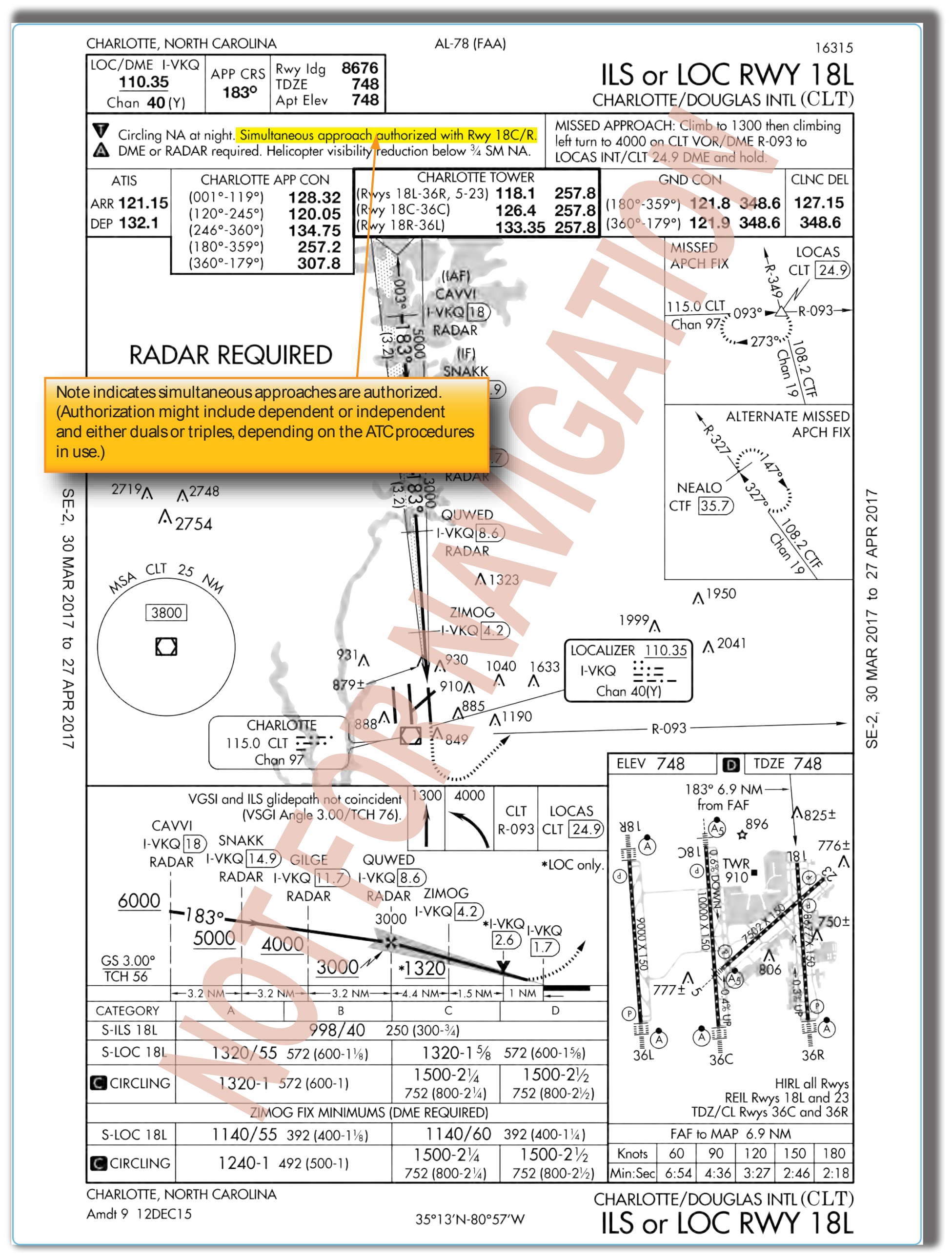
The localizer approach system can provide both precision and non-precision approach capabilities to a pilot. As a part of the ILS system, the localizer provides horizontal guidance for a precision approach. Typically, when the localizer is discussed, it is thought of as a non-precision approach due to the fact that either it is the only approach system installed, or the glideslope is out of service on the ILS. In either case, the localizer provides a non-precision approach using a localizer transmitter installed at a specific airport. [Figure 4-58]
TERPS provides the same alignment criteria for a localizer approach as it does for the ILS, since it is essentially the same approach without vertical guidance stemming from the glideslope. A localizer is always aligned within 3° of the runway, and it is afforded a minimum of 250 feet obstacle clearance in the final approach area. In the case of a localizer DME (LOC DME) approach, the localizer installation has a collocated DME installation that provides distance information required for the approach. [Figure 4-59]