
Chapter 6
Airborne Navigation Databases
- Heading to a manual termination or VM leg— defines a specified heading until a manual termination. [Figure 6-22]
- Heading to a radial termination or VR leg—defines a specified heading to a specified radial from a specific
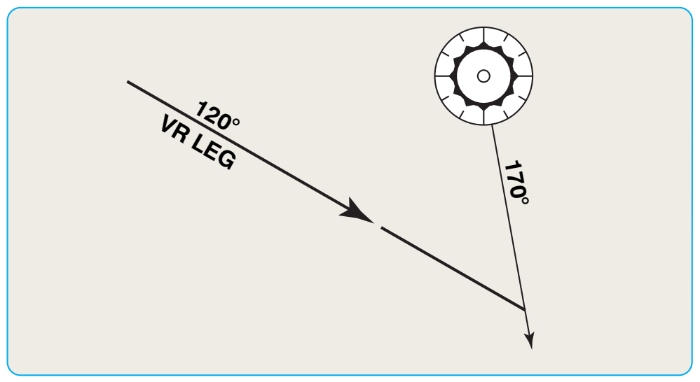
database VOR NAVAID. [Figure 6-23]
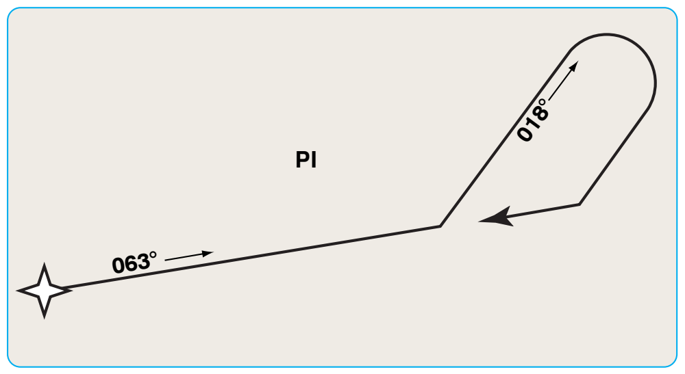
- Procedure turn or PI leg—defines a course reversal starting at a specific database fix and includes outbound leg followed by a left or right turn and 180° course reversal to intercept the next leg. [Figure 6-24]
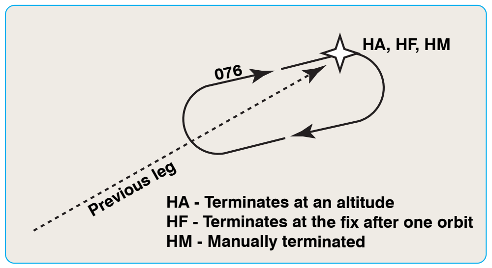
- Racetrack course reversal or altitude termination (HA), single circuit terminating at the fix (base turn) (HF), or manual termination (HM) leg types—define racetrack pattern or course reversals at a specified database fix. [Figure 6-25]
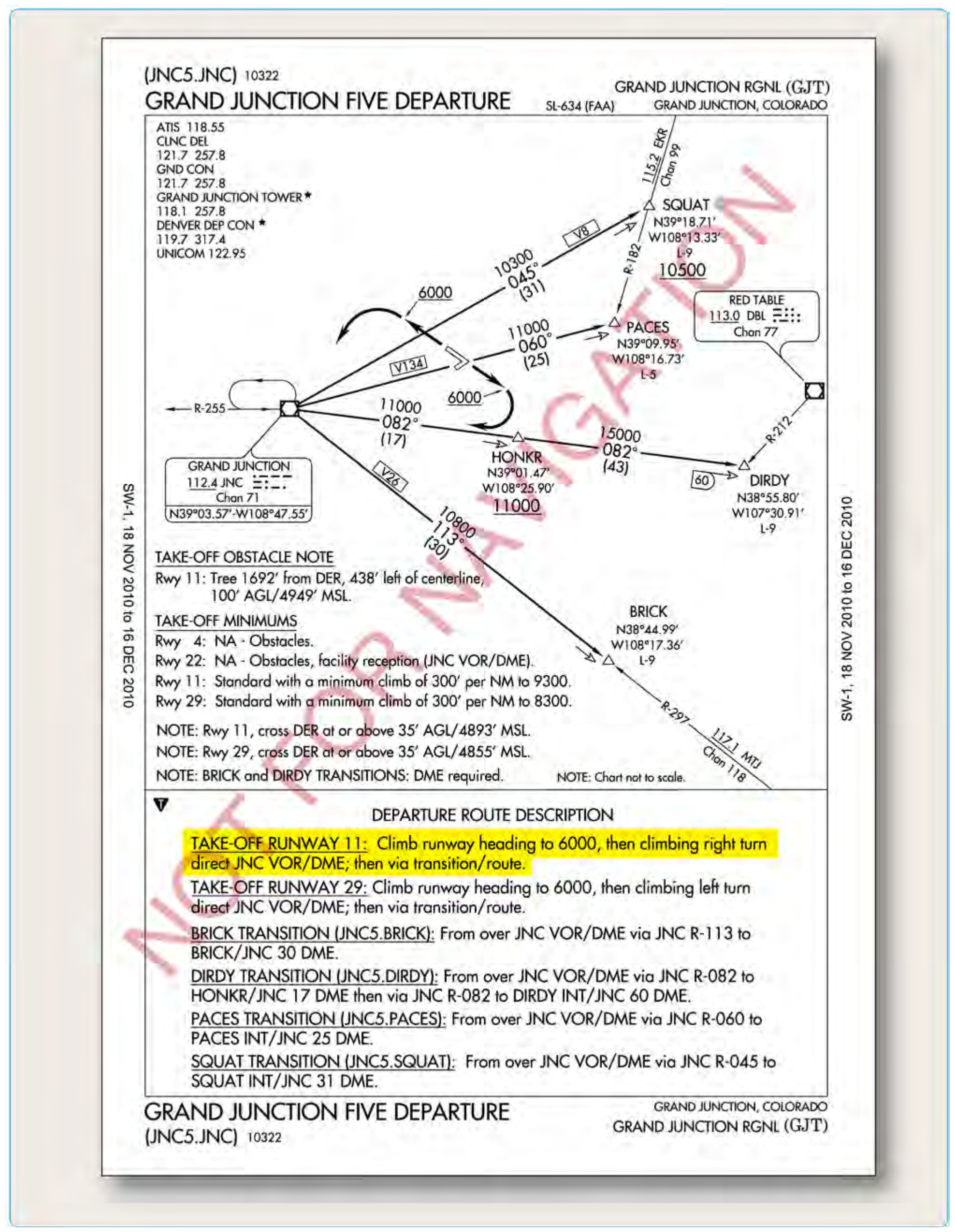
The GRAND JUNCTION FIVE DEPARTURE for Grand Junction Regional in Grand Junction, Colorado, provides a good example of different types of path and terminator legs used. [Figure 6-26] When this procedure is coded into the navigation database, the person entering the data into the records must identify the individual legs of the flightpath and then determine which type of terminator should be used.
The first leg of the departure for Runway 11 is a climb via runway heading to 6,000 feet mean sea level (MSL) and then a climbing right turn direct to a fix. When this is entered into the database, a heading to an altitude (VA) value must be entered into the record’s path and terminator field for the first leg of the departure route. This path and terminator tells the avionics to provide course guidance based on heading, until the aircraft reaches 6,000 feet, and then the system begins providing course guidance for the next leg. After reaching 6,000 feet, the procedure calls for a right turn direct to the Grand Junction (JNC) VORTAC. This leg is coded into the database using the path and terminator direct to a fix (DF) value, which defines an unspecified track starting from an undefined position to a specific database fix.
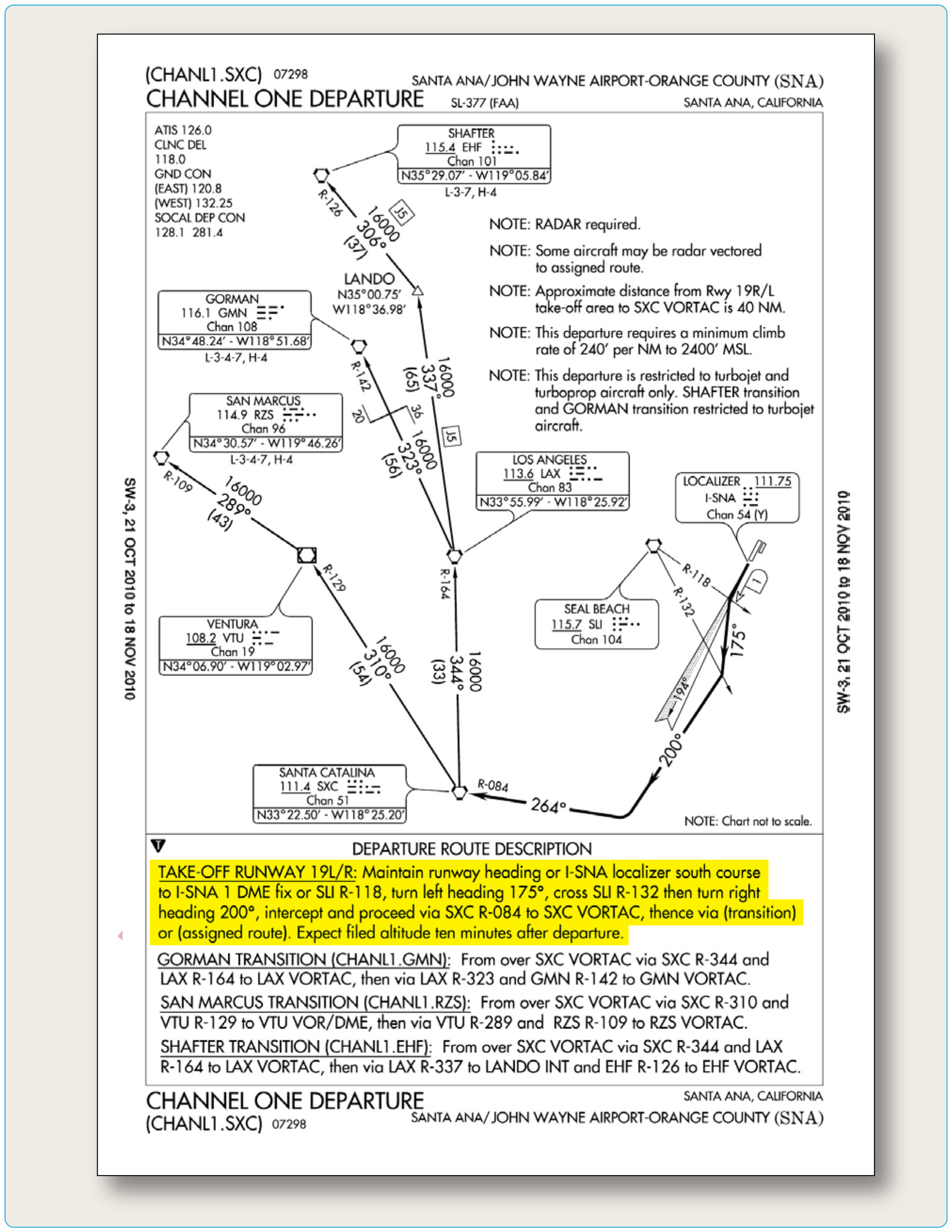
Another commonly used path and terminator value is heading to a radial (VR) which is shown in Figure 6-27 using the CHANNEL ONE DEPARTURE procedure for Santa Ana, California. The first leg of the runway 19L/R procedure requires a climb on runway heading until crossing the I-SNA 1 DME fix or the SLI R-118, this leg must be coded into the database using the VR value in the Path and Terminator field. After crossing the I-SNA 1 DME fix or the SLI R-118, the avionics should cycle to the next leg of the procedure that in this case, is a climb on a heading of 175° until crossing SLI R-132. This leg is also coded with a VR Path and Terminator. The next leg of the procedure consists of a heading of 200° until intercepting the SXC R-084. In order for the avionics to correctly process this leg, the database record must include the heading to an intercept (VI) value in the Path and Terminator field. This value directs the avionics to follow a specified heading to intercept the subsequent leg at an unspecified position.
The path and terminator concept is a very important part of airborne navigation database coding. In general, it is not necessary for pilots to have an in-depth knowledge of the ARINC coding standards; however, pilots should be familiar with the concepts related to coding in order to understand the limitations of specific RNAV systems that use databases.
Path and Terminator Limitations
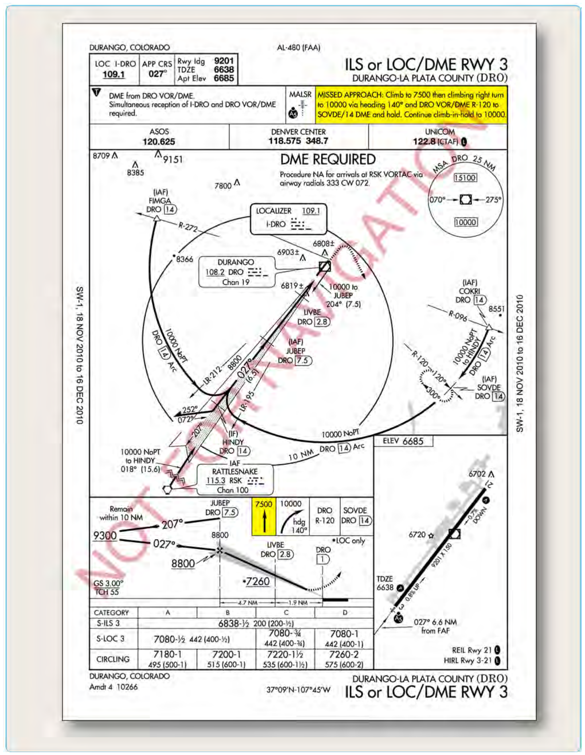
How a specific RNAV system deals with Path and Terminators is of great importance to pilots operating with airborne navigation databases. Some early RNAV systems may ignore this field completely. The ILS or LOC/DME RWY 3 approach at Durango, Colorado, provides an example of problems that may arise from the lack of path and terminator capability in RNAV systems. Although approaches of this type are authorized only for sufficiently equipped RNAV systems, it is possible that a pilot may elect to fly the approach with conventional navigation, and then re-engage RNAV during a missed approach. If this missed approach is flown using an RNAV system that does not use Path and terminator values or the wrong leg types, then the system will most likely ignore the first two legs of the procedure. This will cause the RNAV equipment to direct the pilot to make an immediate turn toward the Durango VOR instead of flying the series of headings that terminate at specific altitudes as dictated by the approach procedure. [Figure 6-28] Pilots must be aware of their individual systems Path and Terminator handling characteristics and always review the manufacturer’s documentation to familiarize themselves with the capabilities of the RNAV equipment they are operating. Pilots should be aware that some RNAV equipment was designed without the fly-over capability which can cause problems for pilots attempting to use this equipment to fly complex flightpaths in the departure, arrival, or approach environments.
Role of the Database Provider
Compiling and maintaining a worldwide airborne navigation database is a large and complex job. Within the United States, the FAA sources give the database providers information, in many different formats, which must be analyzed, edited, and processed before it can be coded into the database. In some cases, data from outside the United States must be translated into English so it may be analyzed and entered into the database. Once the data is coded, it must be continually updated and maintained.
Once the FAA notifies the database provider that a change is necessary, the update process begins. The change is incorporated into a 28-day airborne database revision cycle based on its assigned priority. If the information does not reach the coding phase prior to its cutoff date (the date that new aeronautical information can no longer be included in the next update), it is held out of revision until the next 21 days prior to the effective date of the revision.
The integrity of the data is ensured through a process called cyclic redundancy check (CRC). A CRC is an error detection algorithm capable of detecting small bit-level changes in a block of data. The CRC algorithm treats a data block as a single, large binary value. The data block is divided by a fixed binary number called a generator polynomial whose form and magnitude is determined based on the level of integrity desired. The remainder of the division is the CRC value for the data block. This value is stored and transmitted with the corresponding data block. The integrity of the data is checked by reapplying the CRC algorithm prior to distribution.