
Chapter 11
Helicopter Emergencies
Helicopters with high inertia rotor systems will maintain altitude momentarily after the throttle is closed. Then, as the rotor r.p.m. decreases, the helicopter starts to settle.
When the helicopter has settled to approximately 1 foot above the surface, apply upward collective pitch control while holding the throttle in the closed position to slow the descent and cushion the landing. The timing of collective pitch control application, and the rate at which it is applied, depends upon the particular helicopter being used, its gross weight, and the existing atmospheric conditions. Cyclic control is used to maintain a level attitude and to ensure a vertical descent. Maintain heading with antitorque pedals.
When the weight of the helicopter is entirely on the skids, cease the application of upward collective. When the helicopter has come to a complete stop, lower the collective pitch to the full down position.
The timing of the collective pitch is a most important consideration. If it is applied too soon, the remaining r.p.m. may not be sufficient to make a soft landing. On the other hand, if collective pitch control is applied too late, surface contact may be made before sufficient blade pitch is available to cushion the landing.
Common Errors
- Failing to use sufficient proper antitorque pedal when power is reduced.
- Failing to stop all sideward or backward movement prior to touchdown.
- Failing to apply up-collective pitch properly, resulting in a hard touchdown.
- Failing to touch down in a level attitude.
- Not rolling the throttle completely to idle.
Height/Velocity Diagram
A height/velocity (H/V) diagram, published by the manufacturer for each model of helicopter, depicts the critical combinations of airspeed and altitude should an engine failure occur. Operating at the altitudes and airspeeds shown within the crosshatched or shaded areas of the H/V diagram may not allow enough time for the critical transition from powered flight to autorotation. [Figure 11-2]
An engine failure in a climb after takeoff occurring in section A of the diagram is most critical. During a climb, a helicopter is operating at higher power settings and blade angle of attack. An engine failure at this point causes a rapid rotor r.p.m. decay because the upward movement of the helicopter must be stopped, then a descent established in order to drive the rotor. Time is also needed to stabilize, then increase the r.p.m. to the normal operating range. The rate of descent must reach a value that is normal for the airspeed at the moment.
Since altitude is insufficient for this sequence, you end up with decaying r.p.m., an increasing sink rate, no deceleration lift, little translational lift, and little response to the application of collective pitch to cushion the landing.
It should be noted that, once a steady state autorotation has been established, the H/V diagram no longer applies. An engine failure while descending through section A of the diagram, is less critical, provided a safe landing area is available.
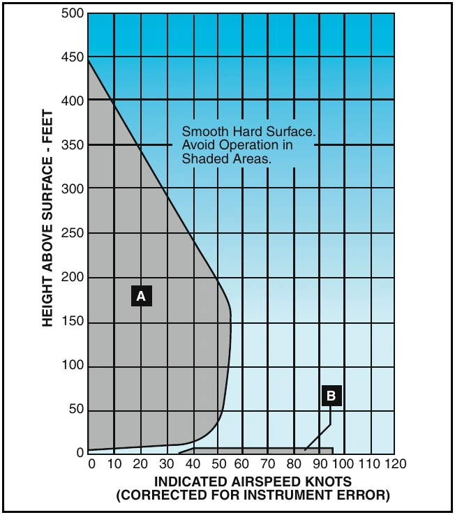
You should avoid the low altitude, high airspeed portion of the diagram (section B), because your recognition of an engine failure will most likely coincide with, or shortly occur after, ground contact. Even if you detect an engine failure, there may not be sufficient time to rotate the helicopter from a nose low, high airspeed attitude to one suitable for slowing, then landing. Additionally, the altitude loss that occurs during recognition of engine failure and rotation to a landing attitude, may not leave enough altitude to prevent the tail skid from hitting the ground during the landing maneuver.
Basically, if the helicopter represented by this H/V diagram is above 445 feet AGL, you have enough time and altitude to enter a steady state autorotation, regardless of your airspeed. If the helicopter is hovering at 5 feet AGL (or less) in normal conditions and the engine fails, a safe hovering autorotation can be made. Between approximately 5 feet and 445 feet AGL, however, the transition to autorotation depends on the altitude and airspeed of the helicopter. Therefore, you should always be familiar with the height/velocity diagram for the particular model of helicopter you are flying.
The Effect of Weight Versus Density Altitude
The height/velocity diagram depicts altitude and airspeed situations from which a successful autorotation can be made. The time required, and therefore, altitude necessary to attain a steady state autorotative descent, is dependent on the weight of the helicopter and the density altitude. For this reason, the H/V diagram for some helicopter models is valid only when the helicopter is operated in accordance with the gross weight vs. density altitude chart. Where appropriate, this chart is found in the rotorcraft flight manual for the particular helicopter. [Figure 11-3]
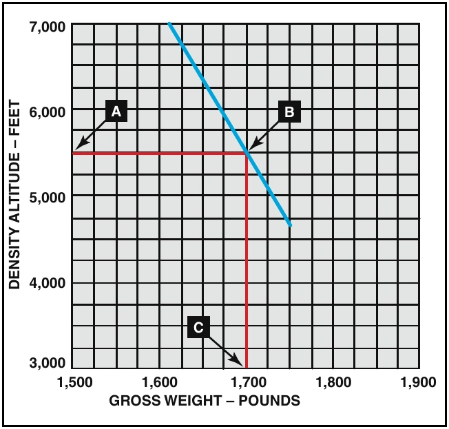
The gross weight vs. density altitude chart is not intended as a restriction to gross weight, but as an advisory to the autorotative capability of the helicopter during takeoff and climb. You must realize, however, that at gross weights above those recommended by the gross weight vs. density altitude chart, the H/V diagram is not restrictive enough.
Vortex Ring State (Settling With Power)
Vortex ring state describes an aerodynamic condition where a helicopter may be in a vertical descent with up to maximum power applied, and little or no cyclic authority. The term “settling with power” comes from the fact that helicopter keeps settling even though full engine power is applied.