
Chapter 16
Aerodynamics of the Gyroplane
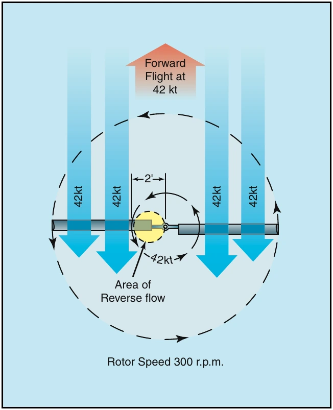
For example, two feet outboard from the rotor hub, the blades travel in a circle with a circumference of 12.6 feet. At a rotor speed of 300 r.p.m., the blade speed at the two-foot station is 42 m.p.h. If the aircraft is being operated at a forward speed of 42 m.p.h., the forward speed of the aircraft essentially negates the rotational velocity on the retreating blade at the two-foot station.
Moving inboard from the two-foot station on the retreating blade, the forward speed of the aircraft increasingly exceeds the rotational velocity of the blade. This causes the airflow to actually strike the trailing edge of the rotor blade, with velocity increasing toward the rotor hub. [Figure 16-6] The size of the area that experiences reverse flow is dependent primarily on the forward speed of the aircraft, with higher speed creating a larger region of reverse flow. To some degree, the operating speed of the rotor system also has an effect on the size of the region, with systems operating at lower r.p.m. being more susceptible to reverse flow and allowing a greater portion of the blade to experience the effect.
Retreating Blade Stall
The retreating blade stall in a gyroplane differs from that of a helicopter in that it occurs outboard from the rotor hub at the 20 to 40 percent position rather than at the blade tip. Because the gyroplane is operating in autorotation, in forward flight there is an inherent stall region centered inboard on the retreating blade. [Refer to figure 16-5] As forward speed increases, the angle of attack on the retreating blade increases to prevent dissymmetry of lift and the stall region moves further outboard on the retreating blade. Because the stalled portion of the rotor disc is inboard rather than near the tip, as with a helicopter, less force is created about the aircraft center of gravity. The result is that you may feel a slight increase in vibration, but you would not experience a large pitch or roll tendency.
Rotor Force
As with any heavier than air aircraft, the four forces acting on the gyroplane in flight are lift, weight, thrust and drag. The gyroplane derives lift from the rotor and thrust directly from the engine through a propeller. [Figure 16-7]
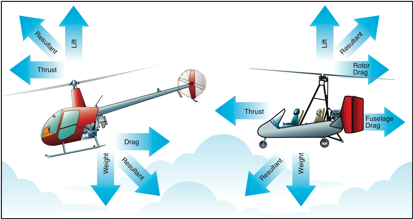
The force produced by the gyroplane rotor may be divided into two components; rotor lift and rotor drag.
The component of rotor force perpendicular to the flight path is rotor lift, and the component of rotor force parallel to the flight path is rotor drag. To derive the total aircraft drag reaction, you must also add the drag of the fuselage to that of the rotor.
Rotor Lift
Rotor lift can most easily be visualized as the lift required to support the weight of the aircraft. When an airfoil produces lift, induced drag is produced. The most efficient angle of attack for a given airfoil produces the most lift for the least drag. However, the airfoil of a rotor blade does not operate at this efficient angle throughout the many changes that occur in each revolution. Also, the rotor system must remain in the autorotative (low) pitch range to continue turning in order to generate lift.
Some gyroplanes use small wings for creating lift when operating at higher cruise speeds. The lift provided by the wings can either supplement or entirely replace rotor lift while creating much less induced drag.
Rotor Drag
Total rotor drag is the summation of all the drag forces acting on the airfoil at each blade position. Each blade position contributes to the total drag according to the speed and angle of the airfoil at that position. As the rotor blades turn, rapid changes occur on the airfoils depending on position, rotor speed, and aircraft speed.
A change in the angle of attack of the rotor disc can effect a rapid and substantial change in total rotor drag.
Rotor drag can be divided into components of induced drag and profile drag. The induced drag is a product of lift, while the profile drag is a function of rotor r.p.m.
Because induced drag is a result of the rotor providing lift, profile drag can be considered the drag of the rotor when it is not producing lift. To visualize profile drag, consider the drag that must be overcome to prerotate the rotor system to flight r.p.m. while the blades are producing no lift. This can be achieved with a rotor system having a symmetrical airfoil and a pitch change capability by setting the blades to a 0° angle of attack.
A rotor system with an asymmetrical airfoil and a built in pitch angle, which includes most amateur-built teeter-head rotor systems, cannot be prerotated without having to overcome the induced drag created as well.