Chapter 18
Gyroplane Systems
More advanced gyroplanes use a prerotator, which provides a mechanical means to spin the rotor. Many prerotators are capable of only achieving a portion of the speed necessary for flight; the remainder is gained by taxiing or during the takeoff roll. Because of the wide variety of prerotation systems available, you need to become thoroughly familiar with the characteristics and techniques associated with your particular system.
Mechanical Prerotator
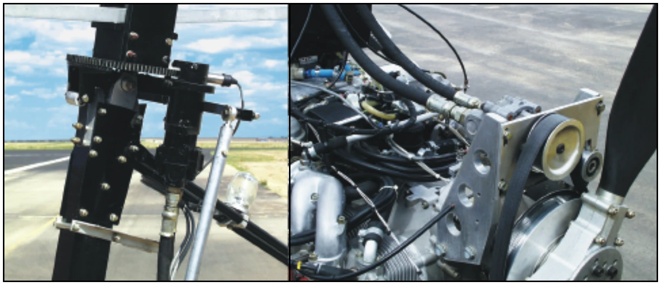
Mechanical prerotators typically have clutches or belts for engagement, a drive train, and may use a transmission to transfer engine power to the rotor. Friction drives and flex cables are used in conjunction with an automotive type bendix and ring gear on many gyroplanes. [Figure 18-3]
The mechanical prerotator used on jump takeoff gyroplanes may be regarded as being similar to the helicopter main rotor drive train, but only operates while the aircraft is firmly on the ground. Gyroplanes do not have an antitorque device like a helicopter, and ground contact is necessary to counteract the torque forces generated by the prerotation system. If jump takeoff capability is designed into a gyroplane, rotor r.p.m. prior to liftoff must be such that rotor energy will support the aircraft through the acceleration phase of takeoff. This combination of rotor system and prerotator utilizes the transmission only while the aircraft is on the ground, allowing the transmission to be disconnected from both the rotor and the engine while in normal flight.
Hydraulic Prerotator
The hydraulic prerotator found on gyroplanes uses engine power to drive a hydraulic pump, which in turn drives a hydraulic motor attached to an automotive type bendix and ring gear. [Figure 18-4] This system also requires that some type of clutch and pressure regulation be incorporated into the design.
Electric Prerotator
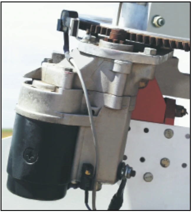
The electric prerotator found on gyroplanes uses an automotive type starter with a bendix and ring gear mounted at the rotor head to impart torque to the rotor system. [Figure 18-5] This system has the advantage of simplicity and ease of operation, but is dependent on having electrical power available. Using a “soft start” device can alleviate the problems associated with the high starting torque initially required to get the rotor system turning. This device delivers electrical pulses to the starter for approximately 10 seconds before connecting uninterrupted voltage.
Tip Jets
Jets located at the rotor blade tips have been used in several applications for prerotation, as well as for hover flight. This system has no requirement for a transmission or clutches. It also has the advantage of not imparting torque to the airframe, allowing the rotor to be powered in flight to give increased climb rates and even the ability to hover. The major disadvantage is the noise generated by the jets. Fortunately, tip jets may be shut down while operating in the autorotative gyroplane mode.
Instrumentation
The instrumentation required for flight is generally related to the complexity of the gyroplane. Some gyroplanes using air-cooled and fuel/oil-lubricated engines may have limited instrumentation.
Engine Instruments
All but the most basic engines require monitoring instrumentation for safe operation. Coolant temperature, cylinder head temperatures, oil temperature, oil pressure, carburetor air temperature, and exhaust gas temperature are all direct indications of engine operation and may be displayed. Engine power is normally indicated by engine r.p.m., or by manifold pressure on gyroplanes with a constant speed propeller.
Rotor Tachometer
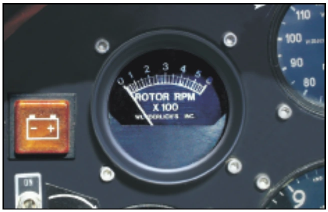
Most gyroplanes are equipped with a rotor r.p.m. indicator. Because the pilot does not normally have direct control of rotor r.p.m. in flight, this instrument is most useful on the takeoff roll to determine when there is sufficient rotor speed for liftoff. On gyroplanes not equipped with a rotor tachometer, additional piloting skills are required to sense rotor r.p.m. prior to takeoff.
Certain gyroplane maneuvers require you to know precisely the speed of the rotor system. Performing a jump takeoff in a gyroplane with collective control is one example, as sufficient rotor energy must be available for the successful outcome of the maneuver. When variable collective and a rotor tachometer are used, more efficient rotor operation may be accomplished by using the lowest practical rotor r.p.m. [Figure 18-6]