
Chapter 2
General Aerodynamics
The difference in surface velocity accounts for a difference in pressure, with the pressure being lower on the top than the bottom. This low pressure area produces an upward force known as the “Magnus Effect.” This mechanically induced circulation illustrates the relationship between circulation and lift.
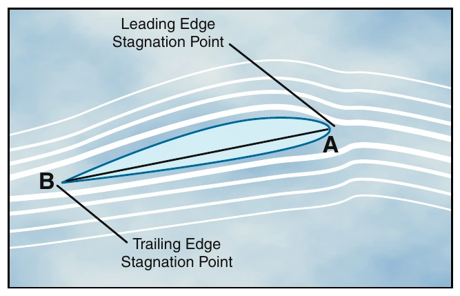
An airfoil with a positive angle of attack develops air circulation as its sharp trailing edge forces the rear stagnation point to be aft of the trailing edge, while the front stagnation point is below the leading edge. [Figure 2-8]
Bernoulli’s Principle
Air flowing over the top surface accelerates. The airfoil is now subjected to Bernoulli’s Principle or the “venturi effect.” As air velocity increases through the constricted portion of a venturi tube, the pressure decreases.
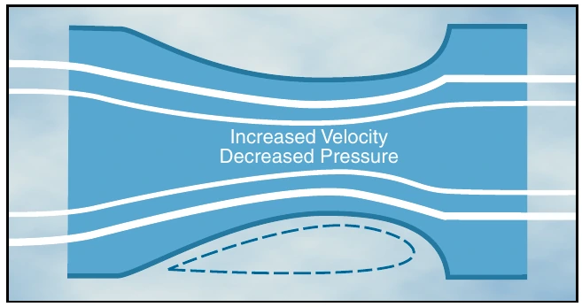
Compare the upper surface of an airfoil with the constriction in a venturi tube that is narrower in the middle than at the ends. [Figure 2-9]
The upper half of the venturi tube can be replaced by layers of undisturbed air. Thus, as air flows over the upper surface of an airfoil, the camber of the airfoil causes an increase in the speed of the airflow. The increased speed of airflow results in a decrease in pressure on the upper surface of the airfoil. At the same time, air flows along the lower surface of the airfoil, building up pressure. The combination of decreased pressure on the upper surface and increased pressure on the lower surface results in an upward force. [Figure 2-10]
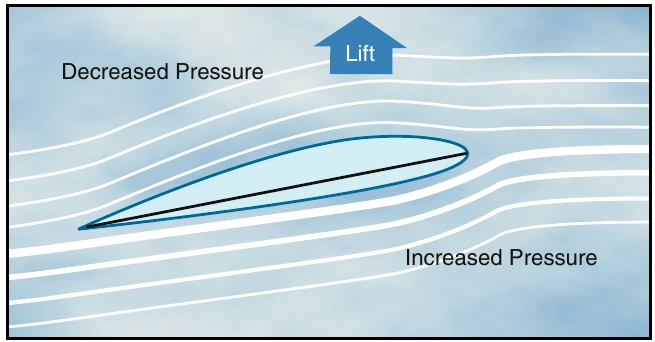
As angle of attack is increased, the production of lift is increased. More upwash is created ahead of the airfoil as the leading edge stagnation point moves under the leading edge, and more downwash is created aft of the trailing edge. Total lift now being produced is perpendicular to relative wind. In summary, the production of lift is based upon the airfoil creating circulation in the airstream (Magnus Effect) and creating differential pressure on the airfoil (Bernoulli’s Principle).
Newton’s Third Law of Motion
Additional lift is provided by the rotor blade’s lower surface as air striking the underside is deflected downward. According to Newton’s Third Law of Motion, “for every action there is an equal and opposite reaction,” the air that is deflected downward also produces an upward (lifting) reaction.
Since air is much like water, the explanation for this source of lift may be compared to the planing effect of skis on water. The lift which supports the water skis (and the skier) is the force caused by the impact pressure and the deflection of water from the lower surfaces of the skis.
Under most flying conditions, the impact pressure and the deflection of air from the lower surface of the rotor blade provides a comparatively small percentage of the total lift. The majority of lift is the result of decreased pressure above the blade, rather than the increased pressure below it.
Weight
Normally, weight is thought of as being a known, fixed value, such as the weight of the helicopter, fuel, and occupants. To lift the helicopter off the ground vertically, the rotor system must generate enough lift to overcome or offset the total weight of the helicopter and its occupants. This is accomplished by increasing the pitch angle of the main rotor blades.
The weight of the helicopter can also be influenced by aerodynamic loads. When you bank a helicopter while maintaining a constant altitude, the “G” load or load factor increases. Load factor is the ratio of the load supported by the main rotor system to the actual weight of the helicopter and its contents. In steady-state flight, the helicopter has a load factor of one, which means the main rotor system is supporting the actual total weight of the helicopter. If you increase the bank angle to 60°, while still maintaining a constant altitude, the load factor increases to two. In this case, the main rotor system has to support twice the weight of the helicopter and its contents. [Figure 2-11]
Disc loading of a helicopter is the ratio of weight to the total main rotor disc area, and is determined by dividing the total helicopter weight by the rotor disc area, which is the area swept by the blades of a rotor. Disc area can be found by using the span of one rotor blade as the radius of a circle and then determining the area the blades encompass during a complete rotation. As the helicopter is maneuvered, disc loading changes.
The higher the loading, the more power you need to maintain rotor speed.
Steady-State Flight— A condition when an aircraft is in straight-and-level, unaccelerated flight, and all forces are in balance.