
Chapter 5
Helicopter Systems
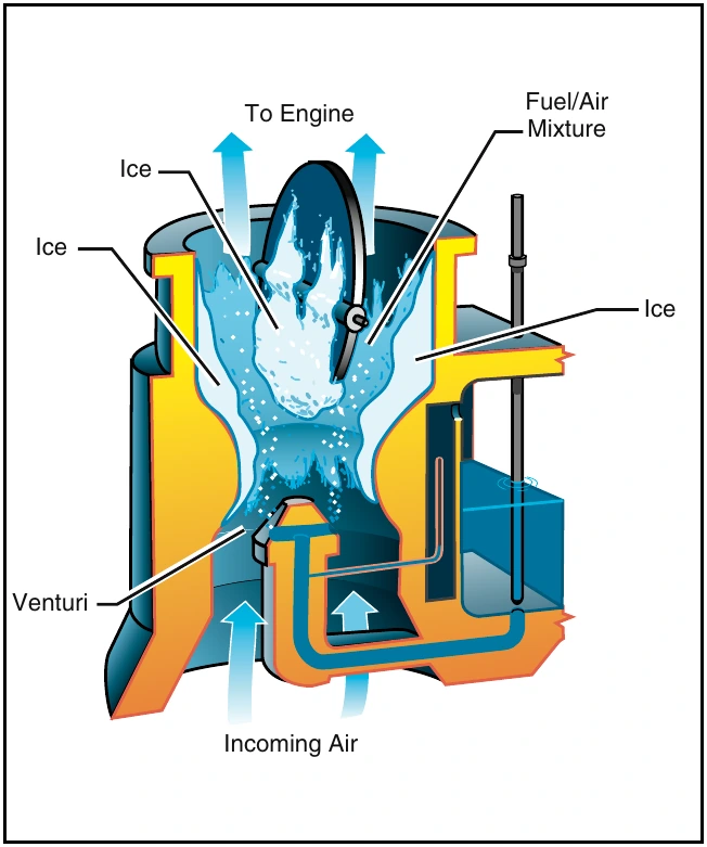
Although carburetor ice can occur during any phase of flight, it is particularly dangerous when you are using reduced power, such as during a descent. You may not notice it during the descent until you try to add power.
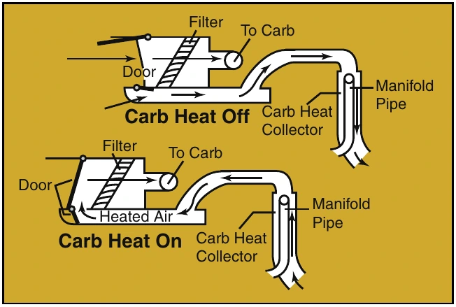
Indications of carburetor icing are a decrease in engine r.p.m. or manifold pressure, the carburetor air temperature gauge indicating a temperature outside the safe operating range, and engine roughness. Since changes in r.p.m. or manifold pressure can occur for a number of reasons, it is best to closely check the carburetor air temperature gauge when in possible carburetor icing conditions. Carburetor air temperature gauges are marked with a yellow caution arc or green operating arcs. You should refer to the FAA-Approved Rotorcraft Flight Manual for the specific procedure as to when and how to apply carburetor heat. However, in most cases, you should keep the needle out of the yellow arc or in the green arc. This is accomplished by using a carburetor heat system, which eliminates the ice by routing air across a heat source, such as an exhaust manifold, before it enters the carburetor. [Figure 5-11].
Fuel Injection
In a fuel injection system, fuel and air are metered at the fuel control unit but are not mixed. The fuel is injected directly into the intake port of the cylinder where it is mixed with the air just before entering the cylinder. This system ensures a more even fuel distribution in the cylinders and better vaporization, which in turn, promotes more efficient use of fuel. Also, the fuel injection system eliminates the problem of carburetor icing and the need for a carburetor heat system.
Turbine Engines
The fuel control system on the turbine engine is fairly complex, as it monitors and adjusts many different parameters on the engine. These adjustments are done automatically and no action is required of the pilot other than starting and shutting down. No mixture adjustment is necessary, and operation is fairly simple as far as the pilot is concerned. New generation fuel controls incorporate the use of a full authority digital engine control (FADEC) computer to control the engine’s fuel requirements. The FADEC systems increase efficiency, reduce engine wear, and also reduce pilot workload. The FADEC usually incorporates back-up systems in the event of computer failure.

Electrical Systems
The electrical systems, in most helicopters, reflect the increased use of sophisticated avionics and other electrical accessories. More and more operations in today’s flight environment are dependent on the aircraft’s electrical system; however, all helicopters can be safely flown without any electrical power in the event of an electrical malfunction or emergency.
Helicopters have either a 14- or 28-volt, direct-current electrical system. On small, piston powered helicopters, electrical energy is supplied by an engine-driven alternator. These alternators have advantages over older style generators as they are lighter in weight, require lower maintenance, and maintain a uniform electrical output even at low engine r.p.m. [Figure 5-12]
Turbine powered helicopters use a starter/generator system. The starter/generator is permanently coupled to the engine gearbox. When starting the engine, electrical power from the battery is supplied to the starter/generator, which turns the engine over. Once the engine is running, the starter/generator is driven by the engine and is then used as a generator.
Current from the alternator or generator is delivered through a voltage regulator to a bus bar. The voltage regulator maintains the constant voltage required by the electrical system by regulating the output of the alternator or generator. An over-voltage control may be incorporated to prevent excessive voltage, which may damage the electrical components. The bus bar serves to distribute the current to the various electrical components of the helicopter.
A battery is mainly used for starting the engine. In addition, it permits limited operation of electrical components, such as radios and lights, without the engine running. The battery is also a valuable source of standby or emergency electrical power in the event of alternator or generator failure.
An ammeter or loadmeter is used to monitor the electrical current within the system. The ammeter reflects current flowing to and from the battery. A charging ammeter indicates that the battery is being charged. This is normal after an engine start since the battery power used in starting is being replaced.
After the battery is charged, the ammeter should stabilize near zero since the alternator or generator is supplying the electrical needs of the system. A discharging ammeter means the electrical load is exceeding the output of the alternator or generator, and the battery is helping to supply electrical power.
This may mean the alternator or generator is malfunctioning, or the electrical load is excessive. A loadmeter displays the load placed on the alternator or generator by the electrical equipment. The RFM for a particular helicopter shows the normal load to expect. Loss of the alternator or generator causes the loadmeter to indicate zero.
Electrical switches are used to select electrical components. Power may be supplied directly to the component or to a relay, which in turn provides power to the component. Relays are used when high current and/or heavy electrical cables are required for a particular component, which may exceed the capacity of the switch.