
Chapter 5
Helicopter Systems
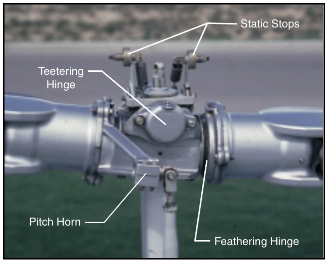
A semirigid rotor system is usually composed of two blades which are rigidly mounted to the main rotor hub.
The main rotor hub is free to tilt with respect to the main rotor shaft on what is known as a teetering hinge. This allows the blades to flap together as a unit. As one blade flaps up, the other flaps down.
Since there is no vertical drag hinge, lead-lag forces are absorbed through blade bending. [Figure 5-6]
Rigid Rotor System
In a rigid rotor system, the blades, hub, and mast are rigid with respect to each other. There are no vertical or horizontal hinges so the blades cannot flap or drag, but they can be feathered. Flapping and lead/lag forces are absorbed by blade bending.
Combination Rotor Systems
Modern rotor systems may use the combined principles of the rotor systems mentioned above. Some rotor hubs incorporate a flexible hub, which allows for blade bending (flexing) without the need for bearings or hinges. These systems, called flextures, are usually constructed from composite material.
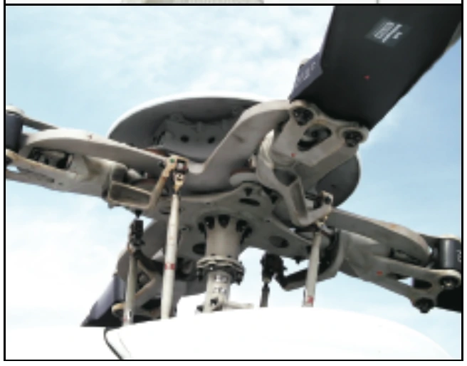
Elastomeric bearings may also be used in place of conventional roller bearings. Elastomeric bearings are bearings constructed from a rubber type material and have limited movement that is perfectly suited for helicopter applications. Flextures and elastomeric bearings require no lubrication and, therefore, require less maintenance. They also absorb vibration, which means less fatigue and longer service life for the helicopter components. [Figure 5-7]
Swash Plate Assembly
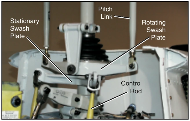
The purpose of the swash plate is to transmit control inputs from the collective and cyclic controls to the main rotor blades. It consists of two main parts: the stationary swash plate and the rotating swash plate. [Figure 5-8] The stationary swash plate is mounted around the main rotor mast and connected to the cyclic and collective controls by a series of pushrods. It is restrained from rotating but is able to tilt in all directions and move vertically. The rotating swash plate is mounted to the stationary swash plate by means of a bearing and is allowed to rotate with the main rotor mast. Both swash plates tilt and slide up and down as one unit. The rotating swash plate is connected to the pitch horns by the pitch links.
Fuel Systems
The fuel system in a helicopter is made up of two groups of components: the fuel supply system and the engine fuel control system.
Fuel Supply System
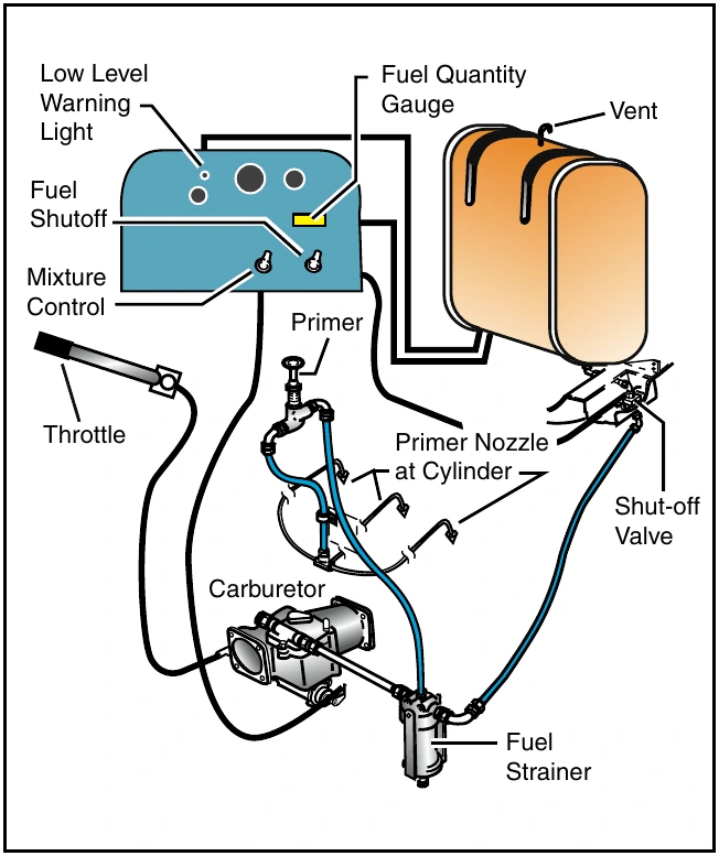
The supply system consists of a fuel tank or tanks, fuel quantity gauges, a shut-off valve, fuel filter, a fuel line to the engine, and possibly a primer and fuel pumps. [Figure 5-9]
The fuel tanks are usually mounted to the airframe as close as possible to the center of gravity. This way, as fuel is burned off, there is a negligible effect on the center of gravity. A drain valve located on the bottom of the fuel tank allows the pilot to drain water and sediment that may have collected in the tank. A fuel vent prevents the formation of a vacuum in the tank, and an overflow drain allows for fuel to expand without rupturing the tank. A fuel quantity gauge located on the pilot’s instrument panel shows the amount of fuel measured by a sensing unit inside the tank. Some gauges show tank capacity in both gallons and pounds.
The fuel travels from the fuel tank through a shut-off valve, which provides a means to completely stop fuel flow to the engine in the event of an emergency or fire.