
Chapter 8
Emergency Open Sea Operations
While the height of the waves is important, it is often less of a consideration than the wavelength, or the distance between swells. Closely spaced swells can be very violent, and can destroy a seaplane even though the wave height is relatively small. On the other hand, the same seaplane might be able to handle much higher waves if the swells are several thousand feet apart. The relationship between the swell length and the height of the waves is the height-to-length ratio [Figure 8-2]. This ratio is an indication of the amount of motion a seaplane experiences on the water and the threat to capsizing. For example, a body of water with 20-foot waves and a swell length of 400 feet has a height-to-length ratio of 1:20, which may not put the seaplane at risk of capsizing, depending on the crosswinds.
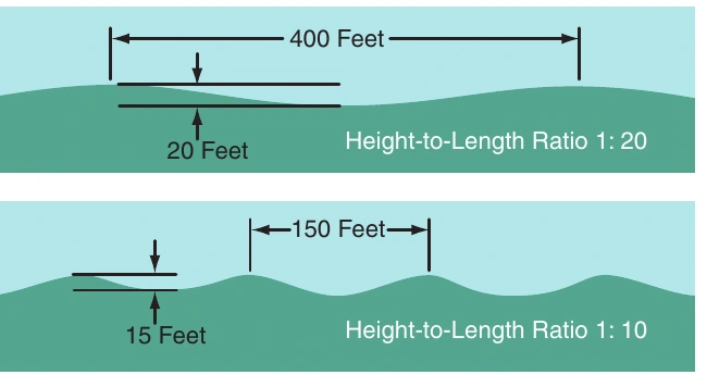
However, 15-foot waves with a length of 150 feet produce a height-to-length ratio of 1:10, which greatly increases the risk of capsizing, especially if the wave is breaking abeam of the seaplane. As the swell length decreases, swell height becomes increasingly critical to capsizing. Thus, when a high swell height-to-length ratio exists, a crosswind takeoff or landing should not be attempted. Downwind takeoff and landing may be made downswell in light and moderate wind; however, a downwind landing should never be attempted when wind velocities are high regardless of swell direction.
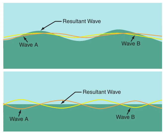
When two swell systems are in phase, the swells act together and result in higher swells. However, when two swell systems are in opposition, the swells tend to cancel each other or “fill in the troughs.” This provides a relatively flat area that appears as a lesser concentration of whitecaps and shadows. This flat area is a good touchdown spot for landing. [Figure 8-3]
Swell System Evaluation
The purpose of the swell system evaluation is to determine the surface conditions and the best heading and technique for landing. Perform a high reconnaissance, a low reconnaissance, and then a final determination of landing heading and touchdown area.
High Reconnaissance
During the high reconnaissance, determine the swell period, swell velocity, and swell length. Perform the high reconnaissance at an altitude of 1,500 to 2,000 feet. Fly straight and level while observing the swell systems. Perform the observation through a complete 360° pattern, rolling out approximately every 45°.
Fly parallel to each swell system and note the heading, the direction of movement of the swell, and the direction of the wind.
To determine the time and distance between crests, and their velocity, follow these directions:
- Drop smoke or a float light and observe the wind condition.
- Time and count the passage of the smoke or float light over successive crests. The number of waves is the number of crests counted minus one. (A complete wave runs from crest to crest. Since the timing starts with a crest and ends with a crest, there is one less wave than crests.) Time and count each swell system.
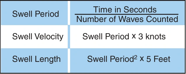
- Obtain the swell period by dividing the time in seconds by the number of waves. For example, 5 waves in 30 seconds equates to a swell period of 6 seconds.
- Determine the swell velocity in knots by multiplying the swell period by 3. In this example, 6 seconds multiplied by 3 equals 18 knots.
- To determine the swell length or distance between crests in feet, multiply the square of the swell period by 5. For example, using a 6-second swell period, 6² multiplied by 5 equals 180 feet. [Figure 8-4]
Low Reconnaissance
Perform the low reconnaissance at 500 feet to confirm the findings of the high reconnaissance and obtain a more accurate estimate of wind direction and velocity.
If the direction of the swell does not agree with the direction noted at 2,000 feet, then there are two swell systems from different directions. The secondary swell system is often moving in the same direction as the wind and may be superimposed on the first swell system. This condition may be indicated by the presence of periodic groups of larger-than-average swells.
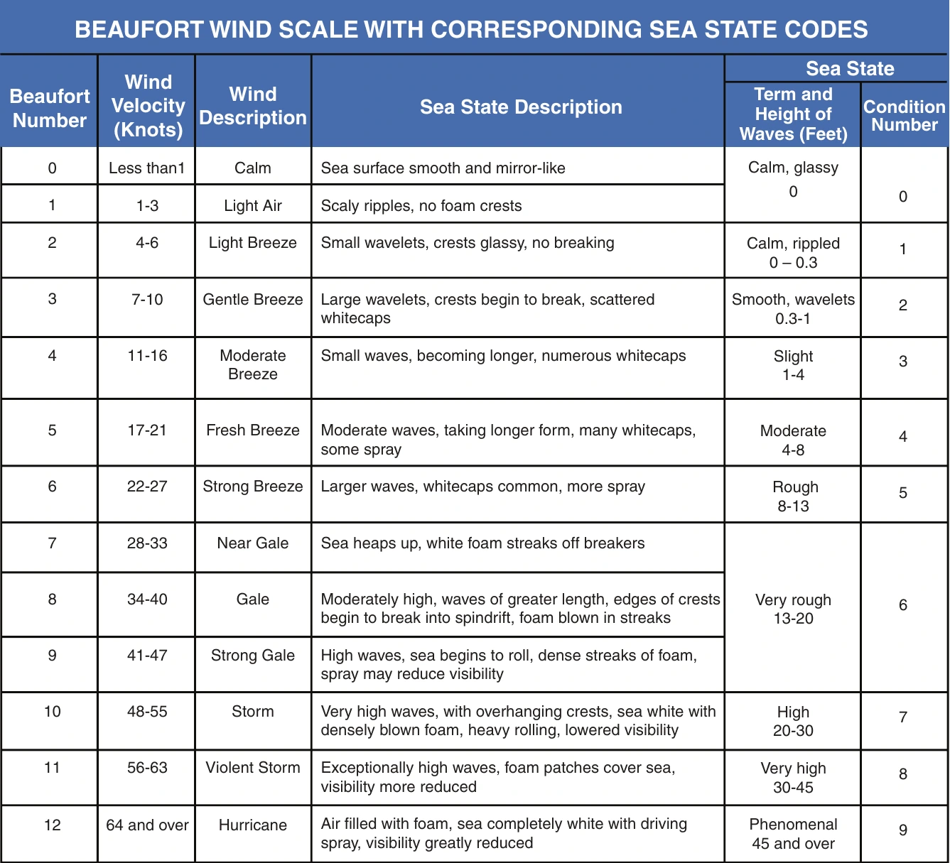
The wind direction and speed can be determined by dropping smoke or observing foam patches, whitecaps, and wind streaks. Whitecaps fall forward with the wind but are overrun by the waves. Thus, the foam patches appear to slide backward into the direction from which the wind is blowing. To estimate wind velocity from sea surface indications, see figure 8-1.
Select Landing Heading
When selecting a landing heading, chart all observed variables and determine the headings that will prove the safest while taking advantage of winds, if possible. Descend to 100 feet and make a final evaluation by flying the various headings and note on which heading the sea appears most favorable. Use the heading that looks smoothest and corresponds with one of the possible headings selected by other criteria.