Chapter 2
Weight and Balance Theory
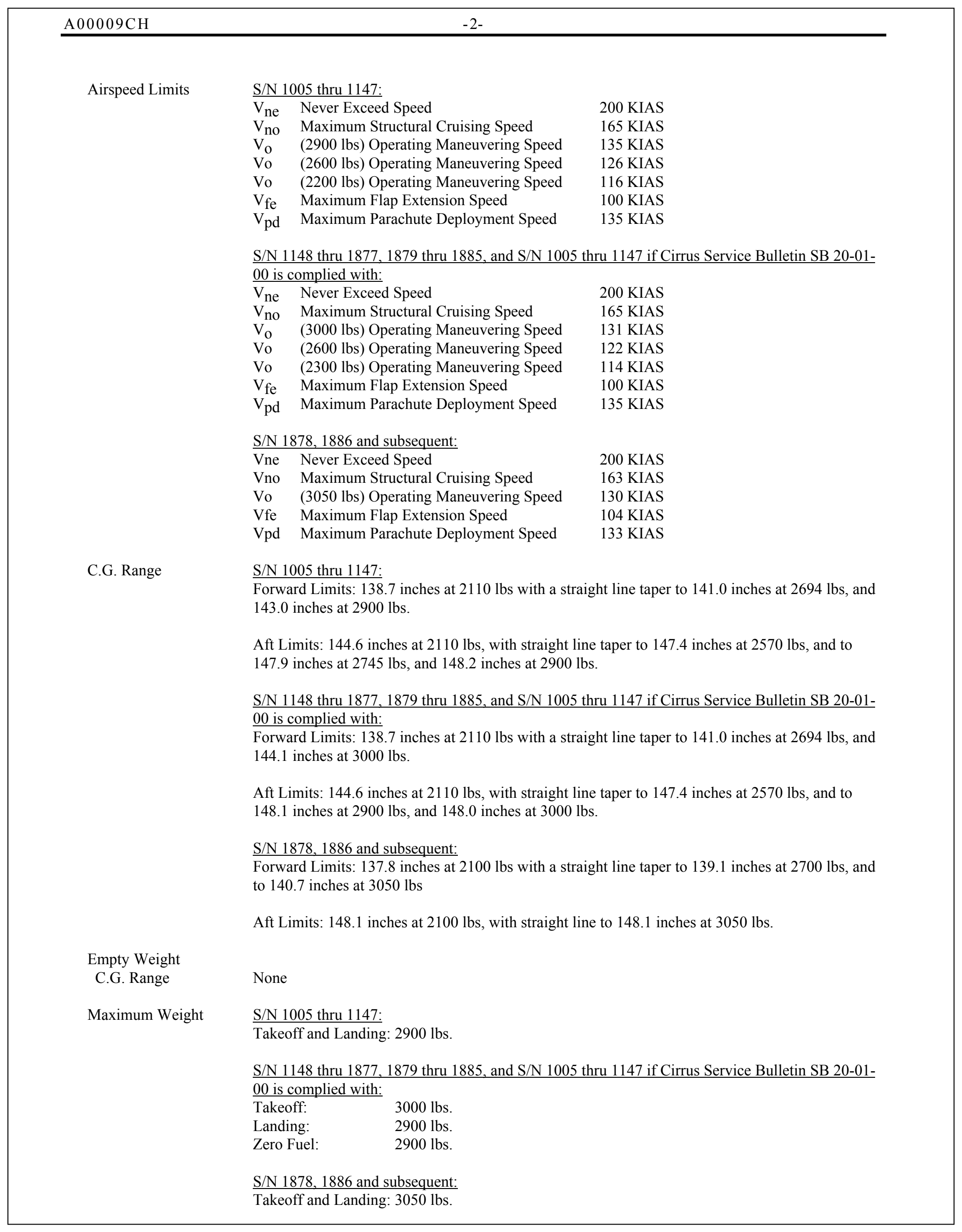
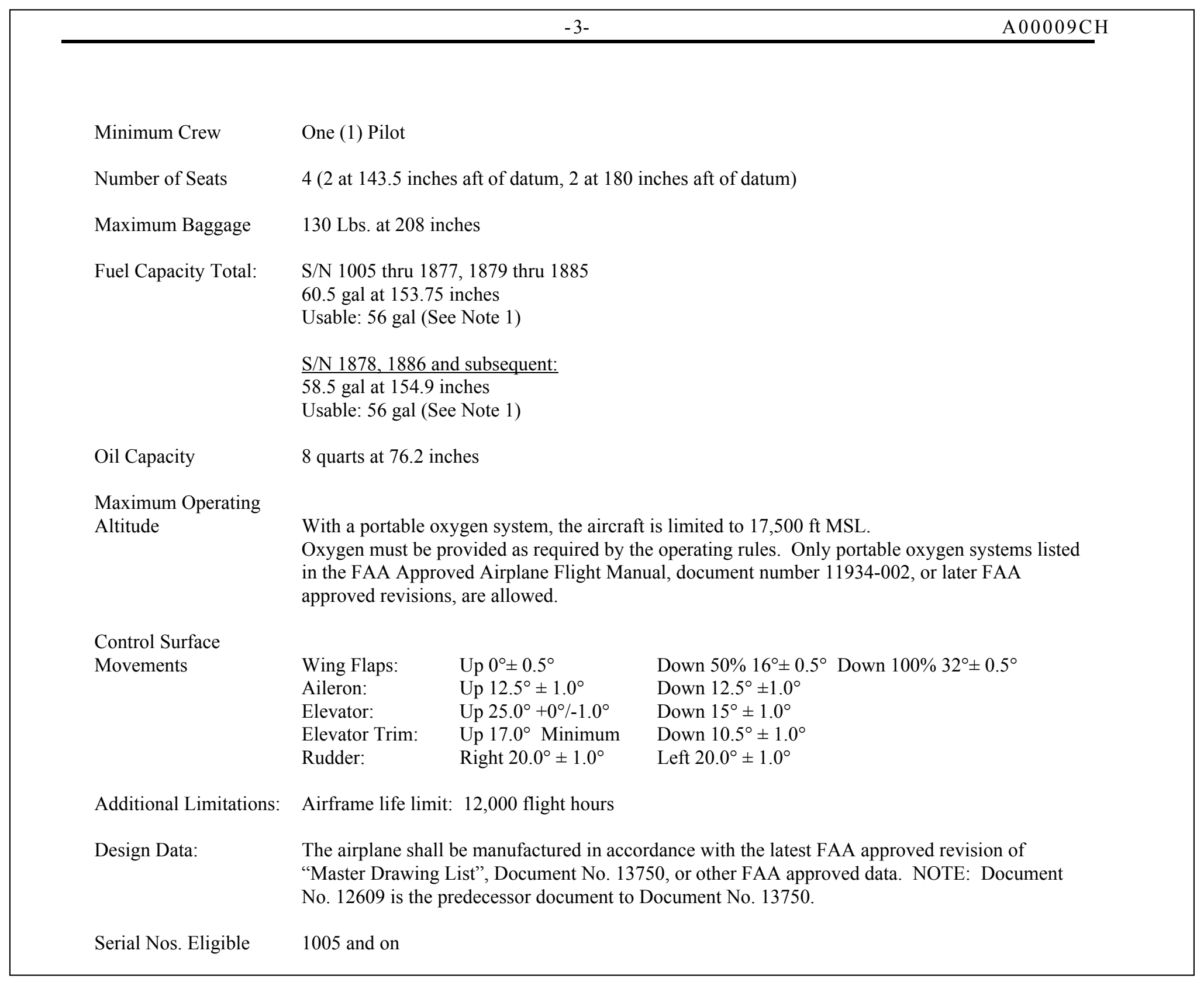
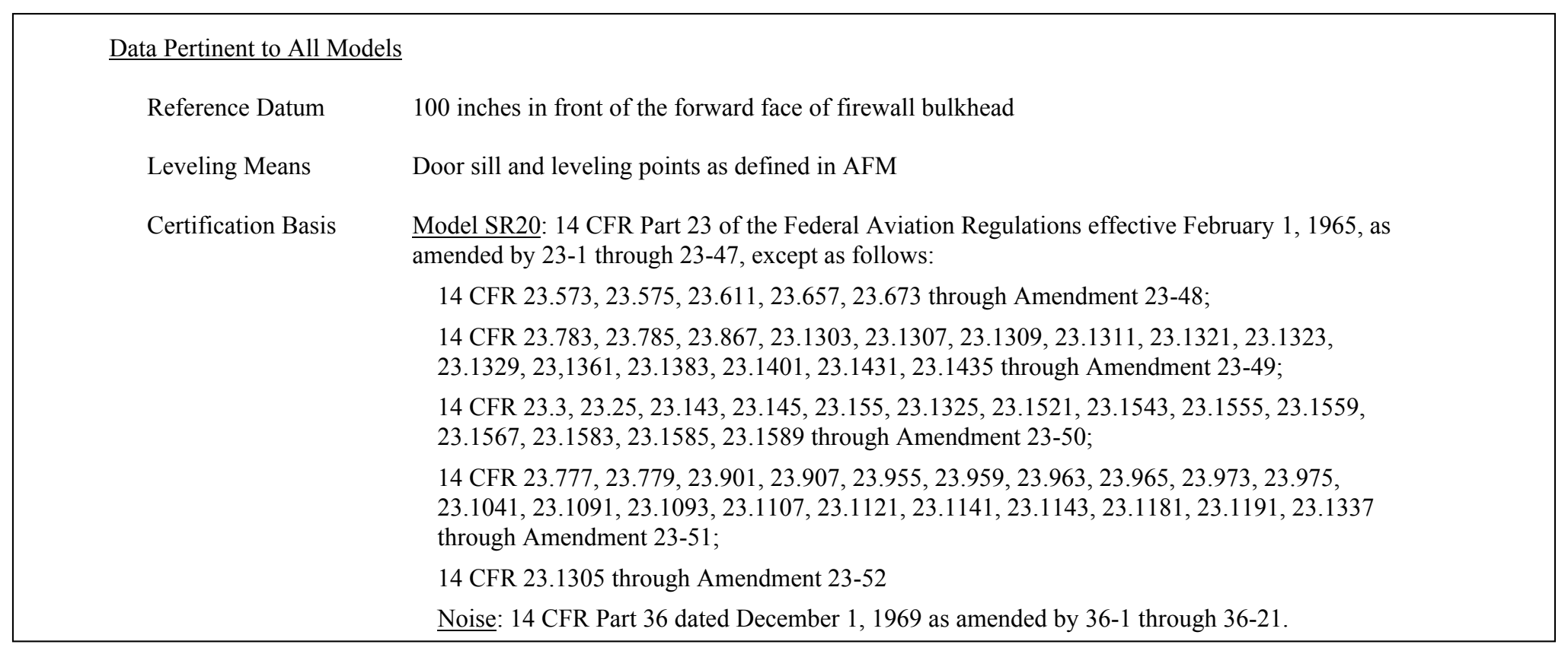
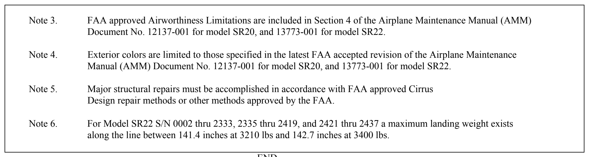
Data Pertinent to all Models
The location of the datum is specified and is described, for example, as: 100 inches in front of the forward face of the firewall bulkhead.
Manufacturer-Furnished Information
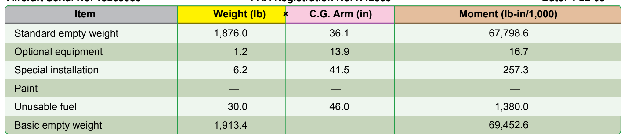
When an aircraft is initially certificated, its empty weight and EWCG are determined and recorded in the weight and balance record, such as the one in Figure 2-16. Notice in this figure that the moment is expressed as “Moment (lb-in/1,000).” This is a moment index, which means that the moment, a very large number, has been divided by 1,000 to make it more manageable. Chapter 4, Weight-Shift-Control, Powered-Parachute, and Amateur-Built Aircraft—Weight and Balance Control, discusses moment indices in more detail.
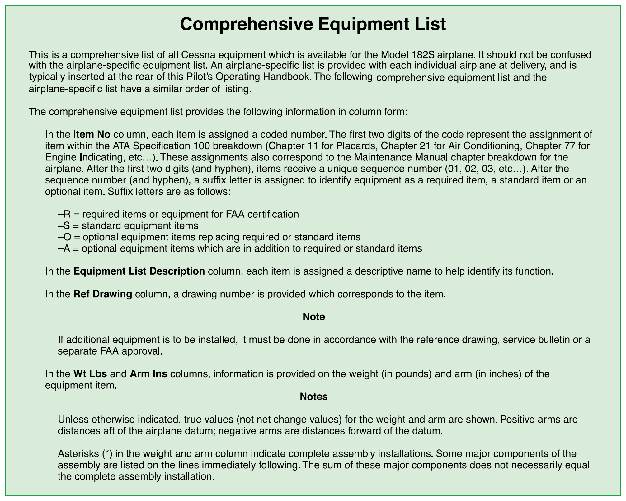
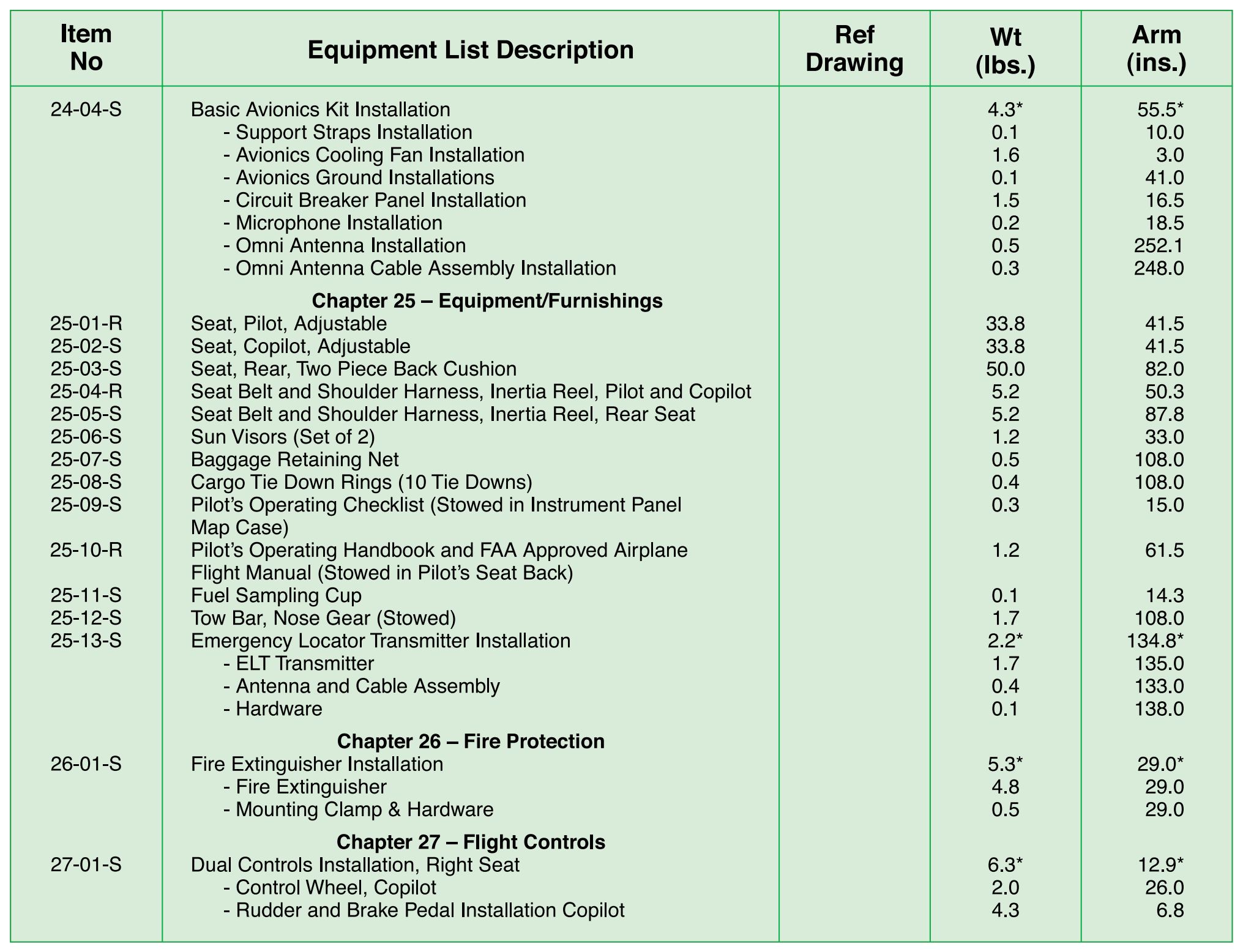
The aircraft is furnished with an equipment list that specifies all the required equipment and all equipment approved for installation in the aircraft. The weight and arm of all installed equipment are included on the list and checked prior to the aircraft leaving the factory. When an aircraft mechanic or repairman adds or removes any item on the equipment list, he or she must change the weight and balance record to indicate the new empty weight and EWCG, and the equipment list is revised to show which equipment is actually installed. Figure 2-17 is from a comprehensive equipment list that includes all of the items of equipment approved for this particular model of aircraft. The pilot’s operating handbook (POH) for each individual aircraft includes an aircraft-specific equipment list of the items from this master list. When any item is added to or removed from the aircraft, its weight and arm are determined in the equipment list and used to update the weight and balance record. The POH and airplane flight manual (AFM) also contain CG moment envelopes and loading graphs. Examples of the use of these helpful graphs are given in Chapter 5, Single-Engine Aircraft Weight and Balance Computations.
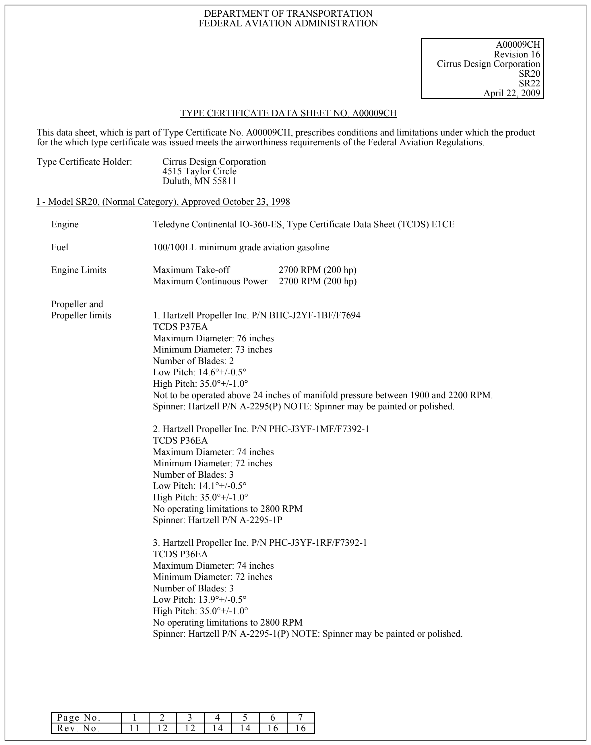
In addition to the weight and balance report and equipment list, the manufacturer also provides a CG range chart. The CG range can be found in text form in the TCDS. The CG range chart is furnished in the POH.