User-friendly explanations of instrument approach charts, planviews, profiles, minimums, airport diagrams, departures, arrivals, and visual procedures.
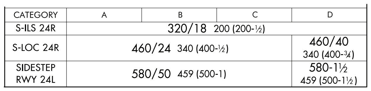
A second category of straight-in minimums called "sidestep" may be depicted where parallel runways exist.
Sidestep minima — S-ILS/S-LOC 24R / Sidestep RWY24L — source page 120.
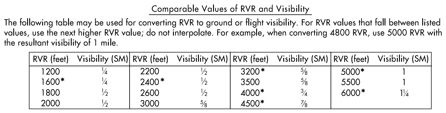
The visibility values are shown after the DA or MDA. They are provided in statue miles or runway visual range (RVR). RVR is reported in hundreds of feet. If the visibility is in statute miles, there is an altitude number, hyphen, whole or fractional number, e.g. 530-1. This indicates 530 feet MSL and 1 statute mile of visibility. The RVR value is separated from the minimum altitude with a slash, e.g., 1540/24. This indicates 1540 feet MSL and RVR of 2400 feet. When an RVR value is shown, the comparable statute mile equivalent is shown within the military minimums in parentheses as shown in the examples above. This value is determined from the Comparable Values of RVR and Visibility table located in the TPP Legend.
Comparable RVR/visibility conversion table — source page 120.
LANDING MINIMUMS The landing minimums section is positioned directly below the profile. This section gives the pilot the lowest altitude and visibility requirements for the approach. There are two types of landing minimums: Straight-in landing or Circling. Straightin landing minimums are the MDA and visibility, or DA and visibility, required for a straight-in landing on a specified runway. Circling minimums are the MDA and visibility required for the circle-to-land maneuver. The minimums for straight-in and circling are located under each aircraft category. When there is not a division line between minimums for each category, the minimums apply to two or more categories. A second category of straight-in minimums called "sidestep" may be depicted where parallel runways exist. The terms used to describe the minimum approach altitudes differ between precision and nonprecision approaches. Precision approaches use DA and nonprecision approaches use MDA, both expressed in feet MSL. The minimum approach altitudes are also referenced to height above touchdown elevation (HAT) for straight-in approaches, or height above airport (HAA) for circling approaches. The figures listed parenthetically are for military operations and are not used in civil aviation. The visibility values are shown after the DA or MDA. They are provided in statue miles or runway visual range (RVR). RVR is reported in hundreds of feet. If the visibility is in statute miles, there is an altitude number, hyphen, whole or fractional number, e.g. 530-1. This indicates 530 feet MSL and 1 statute mile of visibility. The RVR value is separated from the minimum altitude with a slash, e.g., 1540/24. This indicates 1540 feet MSL and RVR of 2400 feet. When an RVR value is shown, the comparable statute mile equivalent is shown within the military minimums in parentheses as shown in the examples above. This value is determined from the Comparable Values of RVR and Visibility table located in the TPP Legend.
Source page 121
If a visibility adjustment is required for a procedure with an RVR value, the RVR value should first be converted to visibility using this table. The visibility should then be increased by the adjustment value, and then may be converted back to the highest RVR value associated with that visibility. For example, if a procedure with 2000 RVR requires a 1/8 mile adjustment, first convert 2000 RVR to 1/2 SM. Adding 1/8 SM results in 5/8 SM, which may then be converted to 3500 RVR.
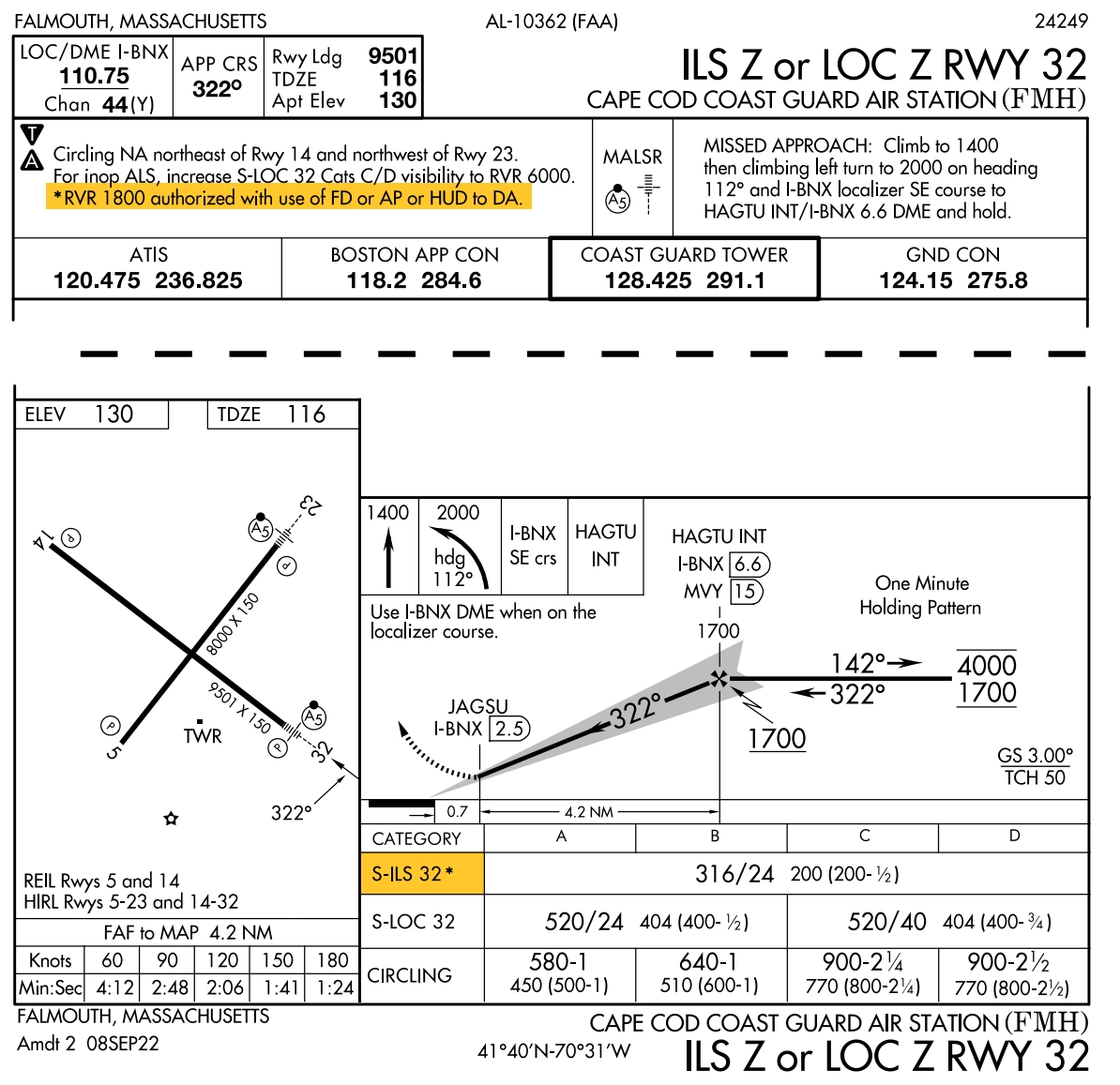
When a reference mark (*, **, #, etc.) is shown on a line of minimums, the qualifying footnote is provided in the notes section.
Airport-sketch example on ILS Z or LOC Z RWY 32 chart — Cape Cod Coast Guard Air Station (FMH) — source page 121.
AIRPORT SKETCH
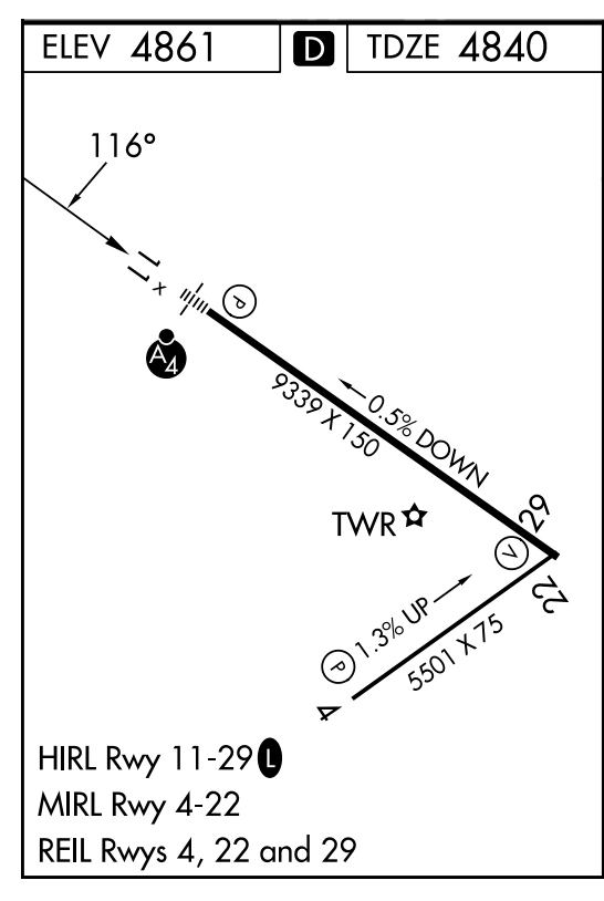
Airport sketch showing runway pattern and lighting information — source page 121.
The airport sketch is a depiction of the airport with emphasis on runway pattern and related information, positioned in either the lower left or lower right corner of the chart to aid pilot recognition of the airport from the air and to provide some information to aid on ground navigation of the airport. The runways are drawn to scale and oriented to true north. Runway dimensions (length and width) are shown for all active runways.
Runway(s) are depicted based on what type and construction of the runway.
Hard SurfaceOther Than Hard SurfaceMetal SurfaceClosed RunwayUnder ConstructionStopways, Taxiways, Parking AreasDisplaced ThresholdClosed PavementWater Runway
Hard Surface | Other Than Hard Surface | Metal Surface | Closed Runway | Under Construction
Stopways, Taxiways, Parking Areas | Displaced Threshold | Closed Pavement | Water Runway |
Hard Surface | Other Than Hard Surface | Metal Surface | Closed Runway | Under Construction
Stopways, Taxiways, Parking Areas | Displaced Threshold | Closed Pavement | Water Runway | — source page 121.
Airport-sketch symbols — stopways/taxiways/parking areas, displaced threshold, closed pavement, and water runway — source page 121.
Taxiways, aprons, and hardstands are only shown at airports that do not have a published airport diagram.Other runway features that may be shown are runway numbers, runway dimensions, runway slope, arresting gear, and displaced threshold.
Other information concerning lighting, airport beacon, control tower, NAVAIDs, and helipads may also be shown. The final approach course or an extension of the final approach course will be shown on all IAPs except ILS CAT II, ILS CAT II & III, ILS SA CAT I, ILS SA CAT II, and ILS SA CAT I & II.
If a visibility adjustment is required for a procedure with an RVR value, the RVR value should first be converted to visibility using this table. The visibility should then be increased by the adjustment value, and then may be converted back to the highest RVR value associated with that visibility. For example, if a procedure with 2000 RVR requires a 1/8 mile adjustment, first convert 2000 RVR to 1/2 SM. Adding 1/8 SM results in 5/8 SM, which may then be converted to 3500 RVR. When a reference mark (*, **, #, etc.) is shown on a line of minimums, the qualifying footnote is provided in the notes section. AIRPORT SKETCH The airport sketch is a depiction of the airport with emphasis on runway pattern and related information, positioned in either the lower left or lower right corner of the chart to aid pilot recognition of the airport from the air and to provide some information to aid on ground navigation of the airport. The runways are drawn to scale and oriented to true north. Runway dimensions (length and width) are shown for all active runways. Runway(s) are depicted based on what type and construction of the runway. Hard Surface Other Than Hard Surface Metal Surface Closed Runway Under Construction Stopways, Taxiways, Parking Areas Displaced Threshold Closed Pavement Water Runway Taxiways, aprons, and hardstands are only shown at airports that do not have a published airport diagram.Other runway features that may be shown are runway numbers, runway dimensions, runway slope, arresting gear, and displaced threshold. Other information concerning lighting, airport beacon, control tower, NAVAIDs, and helipads may also be shown. The final approach course or an extension of the final approach course will be shown on all IAPs except ILS CAT II, ILS CAT II & III, ILS SA CAT I, ILS SA CAT II, and ILS SA CAT I & II.
Cookie Preferences
We use cookies to operate this website, improve performance, understand site traffic, and personalize your experience. Essential cookies are always active because they are required for the website to function.
Required for basic site functionality and security.
Help us understand how visitors use the website so we can improve it.
May be used for advertising, remarketing, or social media features.
You can update your choices anytime using Cookie Settings. View Privacy Policy