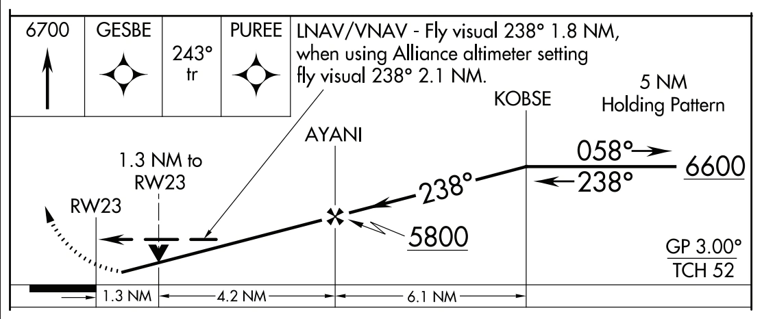
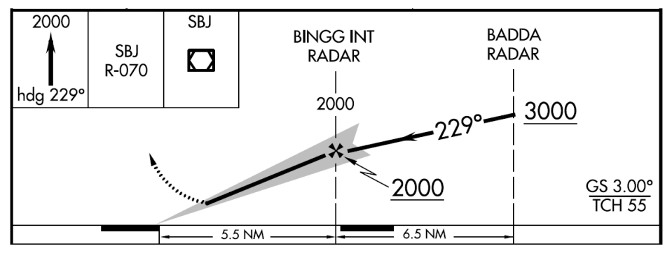
A note providing the glide slope (GS) or glidepath (GP) angle and the threshold crossing height (TCH), are positioned in the lower half of the profile box
GS will be shown on all ILS procedures.
GP will be shown GLS procedures and all RNAV procedures with a published decision altitude
Threshold Crossing Height (TCH) has been traditionally used in “precision” approaches as the height of the glide slope above threshold. With publication of LNAV/VNAV minimums and RNAV descent angles, including graphically depicted descent profiles, TCH also applies to the height of the “descent angle,” or glidepath, at the threshold.
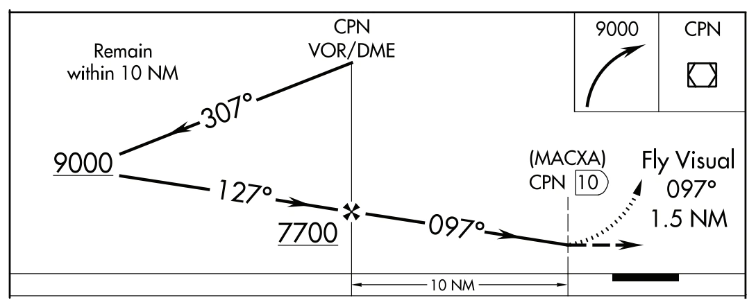
Vertical Descent Angle (VDA) and Threshold Crossing Heights (TCH) A VDA and TCH may be published on non-precision approaches. For Copter approach procedures, a Heliport Crossing Height (HCH) will be depicted in place of the TCH. The VDA is strictly advisory and provides a means to establish a stabilized descent to the MDA. The presence of a VDA does not guarantee obstacle protection in the visual segment. If there are obstacles in the visual segment that could cause an aircraft to destabilize the approach between MDA and touchdown, the profile will not show a VDA and will instead show a note that states “Visual Segment-Obstacles”. Visual Flight Path Instrument approach procedures, including Copter approach procedures, that terminate or have missed approaches prior to the airport, and are authorized to proceed visual, shall depict the visual segment by the dashed line symbol from the missed approach point to the airport. The note “Fly visual” (“Proceed visually” on Copter procedures) along with the bearing and distance shall be shown leadered to the visual flight path. RNAV charts sometimes have visual flight for LNAV/VNAV minima that do not start at the missed approach point. An additional note indicating “LNAV/VNAV” will be placed above the note. Copter approach procedures with a VFR segment from the missed approach point will not depict the VFR segment with a line in the profile. The note similar to “Proceed VFR from MAP” will be shown. Copter VFR Segment Chart Examples Traditional (NAVAID) Approach RNAV Approach ILS Glide Slope and RNAV Glidepath A note providing the glide slope (GS) or glidepath (GP) angle and the threshold crossing height (TCH), are positioned in the lower half of the profile box • GS will be shown on all ILS procedures. • GP will be shown GLS procedures and all RNAV procedures with a published decision altitude Threshold Crossing Height (TCH) has been traditionally used in “precision” approaches as the height of the glide slope above threshold. With publication of LNAV/VNAV minimums and RNAV descent angles, including graphically depicted descent profiles, TCH also applies to the height of the “descent angle,” or glidepath, at the threshold.
Source page 119
34:1 Surface Clear Symbol
On RNAV approach charts, a small shaded arrowhead shaped symbol from the end of the VDA to the runway indicates that the 34:1 Obstacle Clearance Surface (OCS) for the visual segment is clear of obstacles. The absence of the symbol indicates that the 34:1 OCS is not clear or a Visual Segment-Obstacles note is indicated on the chart. (See example in VDP Section.)
Secondary Airports
Airports other than the airport of intended landing will be shown when requested and will be portrayed in the same manner as the primary airport. It will be placed in its approximate location along the final approach course.
34:1 surface-clear symbol in approach profile — source page 119.
34:1 Surface Clear Symbol On RNAV approach charts, a small shaded arrowhead shaped symbol from the end of the VDA to the runway indicates that the 34:1 Obstacle Clearance Surface (OCS) for the visual segment is clear of obstacles. The absence of the symbol indicates that the 34:1 OCS is not clear or a Visual Segment-Obstacles note is indicated on the chart. (See example in VDP Section.) Secondary Airports Airports other than the airport of intended landing will be shown when requested and will be portrayed in the same manner as the primary airport. It will be placed in its approximate location along the final approach course.
Source page 120
LANDING MINIMUMS
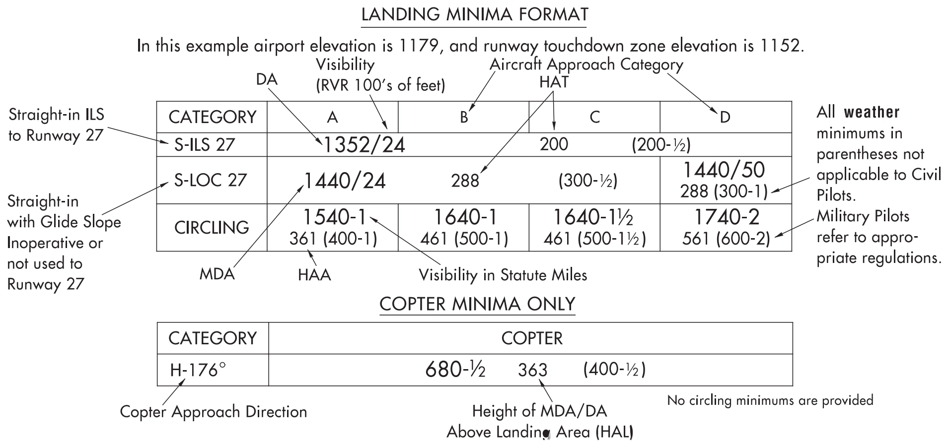
The landing minimums section is positioned directly below the profile. This section gives the pilot the lowest altitude and visibility requirements for the approach. There are two types of landing minimums: Straight-in landing or Circling. Straight-in landing minimums are the MDA and visibility, or DA and visibility, required for a straight-in landing on a specified runway. Circling minimums are the MDA and visibility required for the circle-to-land maneuver.
Landing-minima format — straight-in ILS/LOC, circling, copter callouts — source page 120.
Cookie Preferences
We use cookies to operate this website, improve performance, understand site traffic, and personalize your experience. Essential cookies are always active because they are required for the website to function.
Required for basic site functionality and security.
Help us understand how visitors use the website so we can improve it.
May be used for advertising, remarketing, or social media features.
You can update your choices anytime using Cookie Settings. View Privacy Policy