Searchable VFR Flyway Planning Chart symbols and explanations for pilots.
the VFR flyway routes or
requested by the FAA.
(Normally at least 3000’ paved).
FOREIGN
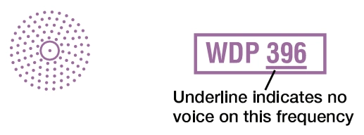
Foreign Airport Note — outside-U.S.-FIR standard symbol and ICAO identifiers — source page 43.
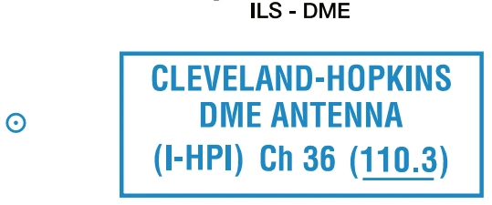
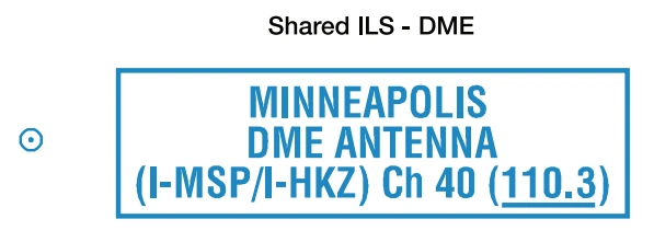
ILS-DME — Cleveland-Hopkins DME antenna (I-HPI), Channel 36 (110.3) — source page 43.
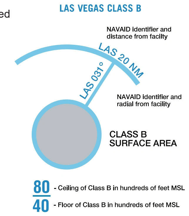
NAVAIDS Used to Define Class Airspace — source page 43.
Foreign-airport symbol — VFR Flyway Planning Charts — source page 43.
VFR FLYWAY PLANNING CHARTS GENERAL INFORMATION VFR Flyway Planning Charts are printed on the reverse sides of the Baltimore-Washington, Charlotte, Chicago, Cincinnati, Dallas-Ft. Worth, Denver, Detroit, Houston, Las Vegas, Los Angeles, Miami, Orlando, New Orleans, Phoenix, St. Louis, Salt Lake City, San Diego, San Francisco, Seattle, and Tampa Terminal Area Charts (TACs). The scale is 1:250,000, with area of coverage the same as the associated TACs. Flyway Planning Charts depict flight paths and altitudes recommended for use to by-pass areas heavily traversed by large turbine-powered aircraft. Ground references on these charts provide a guide for visual orientation. VFR Flyway Planning charts are designed for use in conjunction with TACs and are not to be used for navigation. These charts are updated every 56 days. AIRPORTS Landplane No distinction is made between airports with fuel and those without fuel. Runways may be exaggerated to clearly portray the pattern. Hardsurfaced runways that are closed but still exist are included in the charted pattern. FAR 91 - Fixed wing special VFR operations prohibited. (Pvt): Non-public use having landmark value. “OBJECTIONABLE”: This airport may adversely affect airspace use. RADIO AIDS TO NAVIGATION VHF Omni-Directional Radio Range (VOR) VORTAC VOR-DME DME Example: DME co-located at an airport. Landplane (continued) ABANDONED - Depicted for landmark value or to prevent confusion with an adjacent usable landing area. Only portrayed beneath or close to the VFR flyway routes or requested by the FAA. (Normally at least 3000’ paved). FOREIGN Foreign Airport Note NOTE: Airports outside the U.S. Flight Information Region (FIR) are shown with the standard symbol. Only the airport names and ICAO identifiers are shown. Non-Directional Radio Beacon (NDB) NDB-DME NAVAIDS Used to Define Class Airspace
Source page 44
AIRSPACE INFORMATION
Class B Airspace
Class B airspace — Las Vegas name/radials, altitude notation, and surface-area symbol — source page 44.
Appropriate notes as required
Cookie Preferences
We use cookies to operate this website, improve performance, understand site traffic, and personalize your experience. Essential cookies are always active because they are required for the website to function.
Required for basic site functionality and security.
Help us understand how visitors use the website so we can improve it.
May be used for advertising, remarketing, or social media features.
You can update your choices anytime using Cookie Settings. View Privacy Policy