Searchable explanations of VFR chart terrain, water, obstructions, radio aids, airports, airspace, foreign areas, and chart coverage.
Source page 10
Explanation of VFR Terms and Symbols
This chapter covers the Sectional Aeronautical Chart (Sectional). These charts include the most current data at a scale of (1:500,000), which is large enough to be read easily by pilots flying by sight under Visual Flight Rules. Sectionals are named after a major city within its area of coverage.
The chart legend includes aeronautical symbols and information about drainage, terrain, the contour of the land, and elevation. You can learn to identify aeronautical, topographical, and obstruction symbols (such as radio and television towers) by using the legend.
A brief description next to a small black square indicates the exact location for many of the landmarks easily recognized from the air, such as stadiums, pumping stations, refineries, etc. A small black open circle with descriptive type indicates oil, gas or mineral wells. A small black circle with descriptive type indicates water, oil or gas tanks. The scale for some items may be increased to make them easier to read on the chart.
Aeronautical Information Services' charts are prepared in accordance with specifications of the Interagency Air Committee (IAC) and are approved by representatives of the Federal Aviation Administration (FAA) and the Department of Defense (DoD).
WATER FEATURES (HYDROGRAPHY)
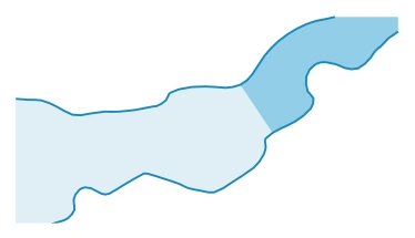
Water features are depicted using two tones of blue, and are considered either "Open Water" or "Inland Water." "Open Water," a lighter blue tone, shows the shoreline limitations of all coastal water features at the average (mean) high water levels for oceans and seas. Light blue also represents the connecting waters like bays, gulfs, sounds and large estuaries.
Exceptionally large lakes like the Great Lakes, Great Salt Lake, and Lake Okeechobee, etc., are considered Open Water features. The Open Water tone extends inland as far as necessary to adjoin the darker blue "Inland Water" tones. All other bodies of water are marked as "Inland Water" in the darker blue tone. — source page 10.
Exceptionally large lakes like the Great Lakes, Great Salt Lake, and Lake Okeechobee, etc., are considered Open Water features. The Open Water tone extends inland as far as necessary to adjoin the darker blue "Inland Water" tones. All other bodies of water are marked as "Inland Water" in the darker blue tone.
LAND FEATURES (TERRAIN) AND OBSTRUCTIONS
The elevation and configuration of the Earth's surface is important to pilots. Our Aeronautical Information Specialists are devoted to showing the contour of the earth and any obstructions clearly and accurately on our charts. We use five different techniques: contour lines, shaded relief, color tints, obstruction symbols, and Maximum Elevation Figures (MEF).
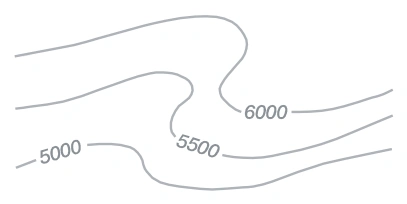
Contour lines join points of equal elevation. On Sectionals, basic contours are spaced at 500' intervals. Intermediate contours are typically at 250' intervals in moderately level or gently rolling areas. Auxiliary contours at 50', 100', 125', or 150' intervals occasionally show smaller relief features in areas of relatively low relief. The pattern of these lines and their spacing gives the pilot a visual concept of the terrain. Widely spaced contours represent gentle slopes, while closely spaced contours represent steep slopes.
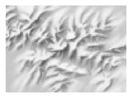
Shaded relief shows how terrain may appear from the air. Shadows are shown as if light is coming from the northwest, because studies have shown that our visual perception has been conditioned to this view.
Different color tints show bands of elevation relative to sea level. These colors range from light green for the lower elevations, to dark brown for the higher elevations.
Obstruction symbols show man made vertical features that could affect safe navigation. The FAA maintains a database of obstacles. Aeronautical Specialists evaluate each obstacle based on charting specifications before adding it to a a visual chart. When a Specialist is not able to verify the position or elevation of an obstacle, it is marked UC, meaning it is "under construction" or being reported, but has not been verified.
1. Contour lines join points of equal elevation. On Sectionals, basic contours are spaced at 500' intervals. Intermediate contours are typically at 250' intervals in moderately level or gently rolling areas. Auxiliary contours at 50', 100', 125', or 150' intervals occasionally show smaller relief features in areas of relatively low relief. The pattern of… — source page 10.
Shaded relief terrain depiction — source page 10.
EXPLANATION OF VFR TERMS AND SYMBOLS This chapter covers the Sectional Aeronautical Chart (Sectional). These charts include the most current data at a scale of (1:500,000), which is large enough to be read easily by pilots flying by sight under Visual Flight Rules. Sectionals are named after a major city within its area of coverage. The chart legend includes aeronautical symbols and information about drainage, terrain, the contour of the land, and elevation. You can learn to identify aeronautical, topographical, and obstruction symbols (such as radio and television towers) by using the legend. A brief description next to a small black square indicates the exact location for many of the landmarks easily recognized from the air, such as stadiums, pumping stations, refineries, etc. A small black open circle with descriptive type indicates oil, gas or mineral wells. A small black circle with descriptive type indicates water, oil or gas tanks. The scale for some items may be increased to make them easier to read on the chart. Aeronautical Information Services' charts are prepared in accordance with specifications of the Interagency Air Committee (IAC) and are approved by representatives of the Federal Aviation Administration (FAA) and the Department of Defense (DoD). WATER FEATURES (HYDROGRAPHY) Water features are depicted using two tones of blue, and are considered either "Open Water" or "Inland Water." "Open Water," a lighter blue tone, shows the shoreline limitations of all coastal water features at the average (mean) high water levels for oceans and seas. Light blue also represents the connecting waters like bays, gulfs, sounds and large estuaries. Exceptionally large lakes like the Great Lakes, Great Salt Lake, and Lake Okeechobee, etc., are considered Open Water features. The Open Water tone extends inland as far as necessary to adjoin the darker blue "Inland Water" tones. All other bodies of water are marked as "Inland Water" in the darker blue tone. LAND FEATURES (TERRAIN) AND OBSTRUCTIONS The elevation and configuration of the Earth's surface is important to pilots. Our Aeronautical Information Specialists are devoted to showing the contour of the earth and any obstructions clearly and accurately on our charts. We use five different techniques: contour lines, shaded relief, color tints, obstruction symbols, and Maximum Elevation Figures (MEF). 1. Contour lines join points of equal elevation. On Sectionals, basic contours are spaced at 500' intervals. Intermediate contours are typically at 250' intervals in moderately level or gently rolling areas. Auxiliary contours at 50', 100', 125', or 150' intervals occasionally show smaller relief features in areas of relatively low relief. The pattern of these lines and their spacing gives the pilot a visual concept of the terrain. Widely spaced contours represent gentle slopes, while closely spaced contours represent steep slopes. 2. Shaded relief shows how terrain may appear from the air. Shadows are shown as if light is coming from the northwest, because studies have shown that our visual perception has been conditioned to this view.
Source page 11
The FAA uses a Digital Obstacle File (DOF) to collect and disseminate data. Because land and obstructions frequently change, the source data on obstructions and terrain is occasionally incomplete or not accurate enough for use in aeronautical publications. For example, when the FAA receives notification about an obstruction, and there is insufficient… — source page 11.
The FAA uses a Digital Obstacle File (DOF) to collect and disseminate data. Because land and obstructions frequently change, the source data on obstructions and terrain is occasionally incomplete or not accurate enough for use in aeronautical publications. For example, when the FAA receives notification about an obstruction, and there is insufficient detail to determine its position and elevation, the FAA Flight Edit Program conducts an investigation.
The Flight Edit crew visually verifies the cultural, topographic, and obstacle data. Charts are generally flight-checked every four years. This review includes checking for any obstruction that has been recently built, altered, or dismantled without proper notification.
Cookie Preferences
We use cookies to operate this website, improve performance, understand site traffic, and personalize your experience. Essential cookies are always active because they are required for the website to function.
Required for basic site functionality and security.
Help us understand how visitors use the website so we can improve it.
May be used for advertising, remarketing, or social media features.
You can update your choices anytime using Cookie Settings. View Privacy Policy