Searchable explanations of VFR chart terrain, water, obstructions, radio aids, airports, airspace, foreign areas, and chart coverage.
1. Determine the elevation of the top of the obstacle above MSL.
2. Add the possible vertical error of the source material to the above figure (100’ or 1/2 contour interval when interval on source exceeds 200’. U.S. Geological Survey Quadrangle Maps with contour intervals as small as 10’ are normally used).
3. Round the resultant figure up to the next… — source page 12.
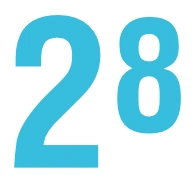
5. The Maximum Elevation Figure (MEF) represents the highest elevation within a quadrant, including terrain and other vertical obstacles (towers, trees, etc.). A quadrant on Sectionals is the area bounded by ticked lines dividing each 30 minutes of latitude and each 30 minutes of longitude. MEF figures are rounded up to the nearest 100' value and the last two digits of the number are not shown. MEFs over land and open water areas are used in areas containing man-made obstacles such as oil rigs. In the determination of MEFs, the FAA uses extreme care to calculate the values based on the existing elevation data shown on source material. Aeronautical Information Specialists use the following procedure to calculate MEFs: MEF - Man-made Obstacle When a man-made obstacle is more than 200' above the highest terrain within the quadrant: 1. Determine the elevation of the top of the obstacle above MSL. 2. Add the possible vertical error of the source material to the above figure (100’ or 1/2 contour interval when interval on source exceeds 200’. U.S. Geological Survey Quadrangle Maps with contour intervals as small as 10’ are normally used). 3. Round the resultant figure up to the next higher hundred-foot level. Example: Elevation of obstacle top (MSL) 2649 Possible obstacle error +100 equals 2749 Raise to the following 100’ level 2800 Maximum Elevation Figure (MEF)
Source page 13
MEF - Natural Terrain Feature or Natural Vertical Obstacle
When a natural terrain feature or natural vertical obstacle (e.g. a tree) is the highest feature within the quadrangle:
Determine the elevation of the feature.
Add the possible vertical error of the source to the above figure (100’ or 1/2 the contour interval when interval on source exceeds 200’).
Add a 200’ allowance for uncharted natural or manmade obstacles. Chart specifications don’t require the portrayal of obstacles below minimum height.
Round the figure up to the next higher hundred-foot level.
1. Determine the elevation of the feature.
2. Add the possible vertical error of the source to the above figure (100’ or 1/2 the contour interval when interval on source exceeds 200’).
3. Add a 200’ allowance for uncharted natural or manmade obstacles. Chart specifications don’t require the portrayal of obstacles below minimum height.
4. Round the figure… — source page 13.
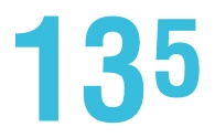
Maximum Elevation Figure (MEF) — 13,500 ft example — source page 13.
LAND FEATURES - MOUNTAIN PASSES
LAND FEATURES - MOUNTAIN PASSES — source page 13.
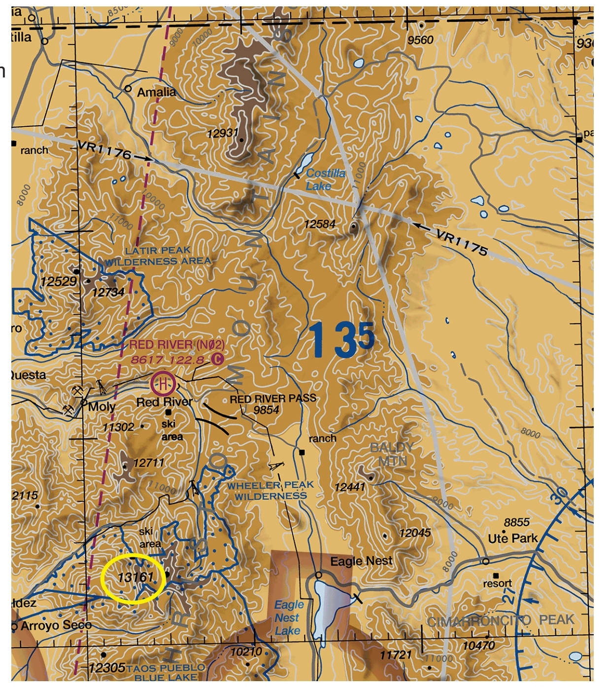
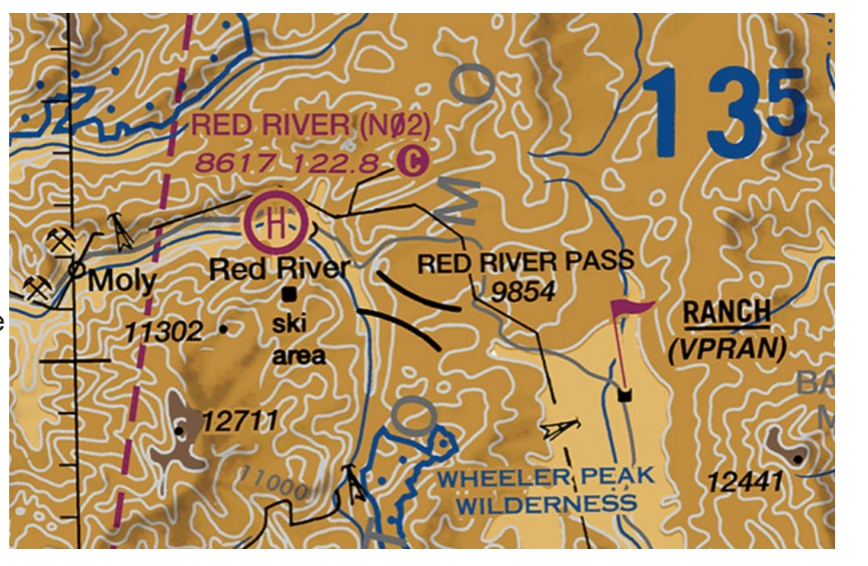
MEF exercise chart excerpt — 13,500-ft MEF near Red River, New Mexico — source page 13.
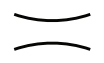
MEF - Natural Terrain Feature or Natural Vertical Obstacle When a natural terrain feature or natural vertical obstacle (e.g. a tree) is the highest feature within the quadrangle: 1. Determine the elevation of the feature. 2. Add the possible vertical error of the source to the above figure (100’ or 1/2 the contour interval when interval on source exceeds 200’). 3. Add a 200’ allowance for uncharted natural or manmade obstacles. Chart specifications don’t require the portrayal of obstacles below minimum height. 4. Round the figure up to the next higher hundredfoot level. Example: Elevation of obstacle top (MSL) 13161 Possible vertical error +100 Obstacle Allowance +200 equals 13461 Raise to the following 100’ level 13500 Maximum Elevation Figure (MEF) Pilots should be aware that while the MEF is based on the best information available to the Specialist, the figures are not verified by field surveys. Also, users should consult the Aeronautical Information Services website to ensure that your chart has the latest MEF data available. LAND FEATURES - MOUNTAIN PASSES The Mountain Pass symbol does not indicate a recommended route or direction of flight, and pass elevation does not indicate a recommended clearance altitude. Hazardous flight conditions may exist within and near mountain passes. For high-traffic mountain passes, VFR Checkpoints may be provided to increase situational awareness by indicating key landmarks inside confined terrain. A collocated VFR Waypoint and Checkpoint may be provided to assist with identifying natural entry points for commonly flown mountain passes.
Source page 14
RADIO AIDS TO NAVIGATION
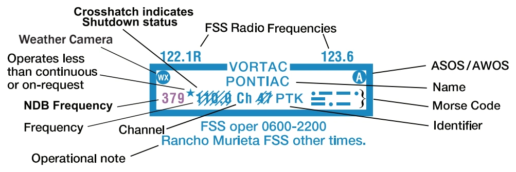
On VFR Charts, information about radio aids to navigation (NAVAID) are boxed, as illustrated. Duplication of data is avoided. When two or more radio aids in a general area have the same name with different frequencies, Tactical Air Navigation (TACAN) channel numbers, or identification letters, and no misinterpretation can result, the name of the radio aid may be indicated only once within the identification box. Very High Frequency/Ultra High Frequency (VHF/UHF) NAVAID names and identification boxes (shown in blue) take precedence. Only those items that differ (e.g., frequency, Morse Code) are repeated in the box in the appropriate color. The choice of separate or combined boxes is made in each case on the basis of economy of space and clear identification of the radio aids.
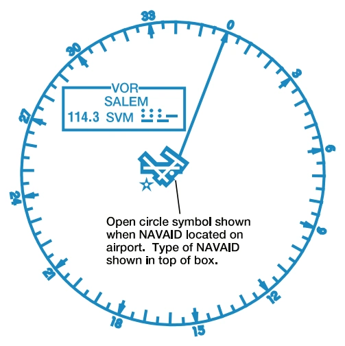
A NAVAID that is physically located on an airport may not always be represented as a typical NAVAID symbol. A small open circle indicates the NAVAID location when collocated with an airport icon. — source page 14.
A NAVAID that is physically located on an airport may not always be represented as a typical NAVAID symbol. A small open circle indicates the NAVAID location when collocated with an airport icon.
The type of NAVAID will be identified by: "VOR," (VHF Omni-Directional Range) "VORTAC" (VOR Tactical Aircraft Control), "VOR-DME," (VOR-Distance Measuring Equipment) or “DME” (Distance Measuring Equipment) positioned on and breaking the top line of the NAVAID box. — source page 14.
The type of NAVAID will be identified by: "VOR," (VHF Omni-Directional Range) "VORTAC" (VOR Tactical Aircraft Control), "VOR-DME," (VOR-Distance Measuring Equipment) or “DME” (Distance Measuring Equipment) positioned on and breaking the top line of the NAVAID box.
AIRPORTS
Cookie Preferences
We use cookies to operate this website, improve performance, understand site traffic, and personalize your experience. Essential cookies are always active because they are required for the website to function.
Required for basic site functionality and security.
Help us understand how visitors use the website so we can improve it.
May be used for advertising, remarketing, or social media features.
You can update your choices anytime using Cookie Settings. View Privacy Policy