Searchable explanations of VFR chart terrain, water, obstructions, radio aids, airports, airspace, foreign areas, and chart coverage.
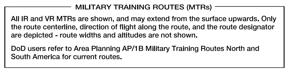
Military Training Route charting guidance note — source page 18.
National Security Areas indicated with a broken magenta line and Special Flight Rules Areas (SFRAs) indicated with the following symbol:, consist of airspace with defined vertical and lateral dimensions established at locations where there is a requirement for increased security and safety of ground facilities. Pilots should avoid flying through these depicted areas. When necessary, flight may be temporarily prohibited. The Washington DC Flight Restricted Zone (FRZ) is related to National Security. It is depicted using the Prohibited/ Restricted/Warning Area symbology and is located within the SFRA. It is defined as the airspace within approximately a 13 to 15 NM radius of the DCA VOR-DME. Additional requirements are levied upon aviators requesting access to operate inside the National Capital Region. Temporary Flight Restriction (TFR) Areas Relating to National Security are indicated with a broken blue line. A Temporary Flight Restriction (TFR) is a type of Notice to Airmen (NOTAM). A TFR defines an area where air travel is restricted due to a hazardous condition, a special event, or a general warning for the entire airspace. The text of the actual TFR contains the fine points of the restriction. It is important to note that only TFRs relating to National Security are charted. Air Defense Identification Zones (ADIZs) are symbolized using the ADIZ symbol:. As defined in Code of Federal Regulations 14 (CFR 14) Part 99, an ADIZ is an area in which the ready identification, location, and control of all aircraft is required in the interest of national security. ADIZ boundaries include Alaska, Hawaii, Guam and the Contiguous U.S. National Defense Airspace Temporary Flight Restriction (TFR) Areas are bounded with cross hatching:. These areas include airspace that is subject to routine TFRs published as NOTAMs that have a 12+ month duration. Terminal Radar Service Areas (TRSAs) are shown in their entirety, symbolized by a screened black outline of the entire area including the various sectors within the area. The outer limit of the entire Terminal Radar Service Areas (TRSA) is a continuous screened black line. The various sectors within the TRSA are symbolized by narrower screened black lines. Each sector altitude is identified in solid black color by the MSL ceiling and floor values of the respective sector, eliminating the last two zeros. A leader line is used when the altitude values must be positioned outside the respective sectors because of charting space limitations. The TRSA name is shown near the north position of the TRSA as follows:. Associated frequencies are listed in a table on the chart border. Military Training Routes (MTRs) are shown on Sectionals and TACs. They are identified by the route designator:. Route designators are shown in solid black on the route centerline, positioned along the route for continuity. The designator IR or VR is not repeated when two or more routes are established over the same airspace, e.g., IR201-205-227. Routes numbered 001 to 099 are shown as IR1 or VR99, eliminating the initial zeros. Direction of flight along the route is indicated by small arrowheads adjacent to and in conjunction with each route designator. The following note appears on Helicopters, Sectionals and TACs except for Hawaiian Islands, which is different. There are IFR (IR) and VFR (VR) routes as follows: Route identification: a. MTRs with no segment above 1500' are identified by four-digit numbers; e.g., VR1007, etc. These routes are generally developed to be flown under Visual Flight Rules. b. MTRs that include one or more segments above 1500' AGL are identified by three or fewer digit numbers; e.g., IR21, etc. These routes are developed to be flown, to the maximum extent possible under Instrument Flight Rules. FAA Chart Users Guide - VFR Terms and Symbols
Source page 19
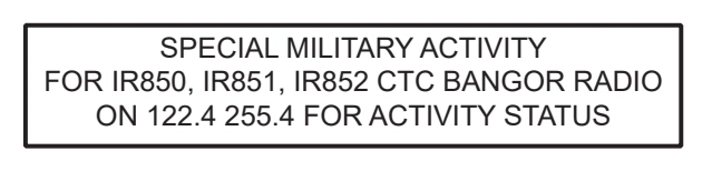
Special Military Activity frequency/status box — source page 19.
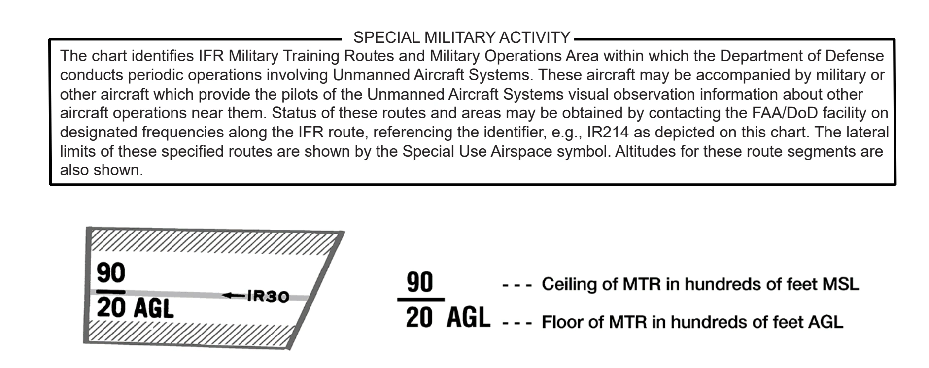
Sectional-margin Special Military Activity guidance and MTR altitude notation — source page 19.
FOREIGN AREAS
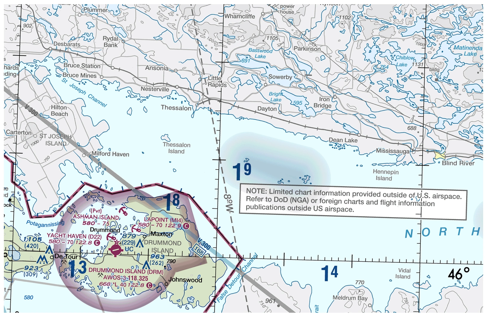
Foreign-area chart-depiction example — source page 19.
FAA Chart Users Guide - VFR Terms and Symbols Route width varies for each MTR and can extend several miles on either side of the charted MTR centerline. Detailed route width information is available in the Flight Information Publication (FLIP) AP/1B (a Department of Defense publication), or through the 56 Day NASR Subscription from the National Flight Data Center (NFDC). Special Military Activity areas are indicated on Sectionals by an underlying IFR Military Training Route with the lateral limits of the route shown by a gray Special Use Airspace symbol. A boxed note accompanies the area. The note contains radio frequency and route identifier information to use for obtaining area activity status. SPECIAL MILITARY ACTIVITY FOR IR850, IR851, IR852 CTC BANGOR RADIO ON 122.4 255.4 FOR ACTIVITY STATUS The following guidance appears in the margin of applicable Sectional Charts. The chart identifies IFR Military Training Routes and Military Operations Area within which the Department of Defense conducts periodic operations involving Unmanned Aircraft Systems. These aircraft may be accompanied by military or other aircraft which provide the pilots of the Unmanned Aircraft Systems visual observation information about other aircraft operations near them. Status of these routes and areas may be obtained by contacting the FAA/DoD facility on designated frequencies along the IFR route, referencing the identifier, e.g., IR214 as depicted on this chart. The lateral limits of these specified routes are shown by the Special Use Airspace symbol. Altitudes for these route segments are also shown. SPECIAL MILITARY ACTIVITY FOREIGN AREAS The data depicted in areas outside the U.S. is skeletonized on all VFR aeronautical charts. Only major airports, NAVAIDs, and airways are charted in foreign areas in screened black. Cultural features, hydrographic information and geographic relief are depicted in subdued and different shades of gray. A note regarding the expectation of the use of foreign charts and flight information publications is depicted along the boundary.
Source page 20
TERMINAL AREA CHART (TAC) COVERAGE
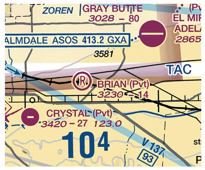
Los Angeles Terminal Area Chart coverage note — source page 20.
TAC boundary/chart excerpt — Los Angeles Terminal Area — source page 20.
INSET AND SPECIAL CHART COVERAGE
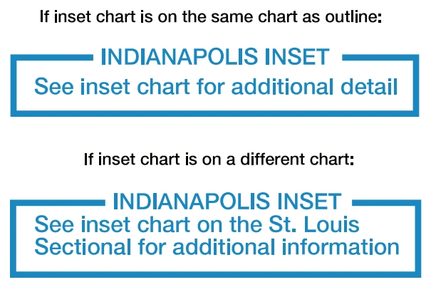
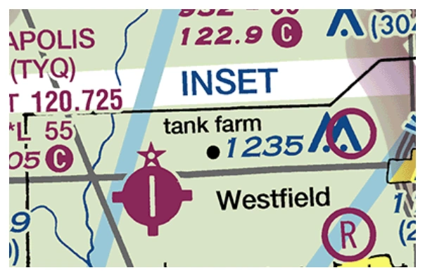
Inset and Special Chart Coverage (.i.e., Grand Canyon Chart) is shown on appropriate Sectionals by a 1/8" masked line as indicated below. A note to this effect appears near the masked boundary line. (Additional examples shown in VFR Sectional and Terminal Charts > Navigational and Procedural Information > Chart Limits.)
Inset-chart notes — same-chart and different-chart variants — source page 20.
Inset-chart excerpt — Indianapolis inset — source page 20.
CHART TABULATIONS
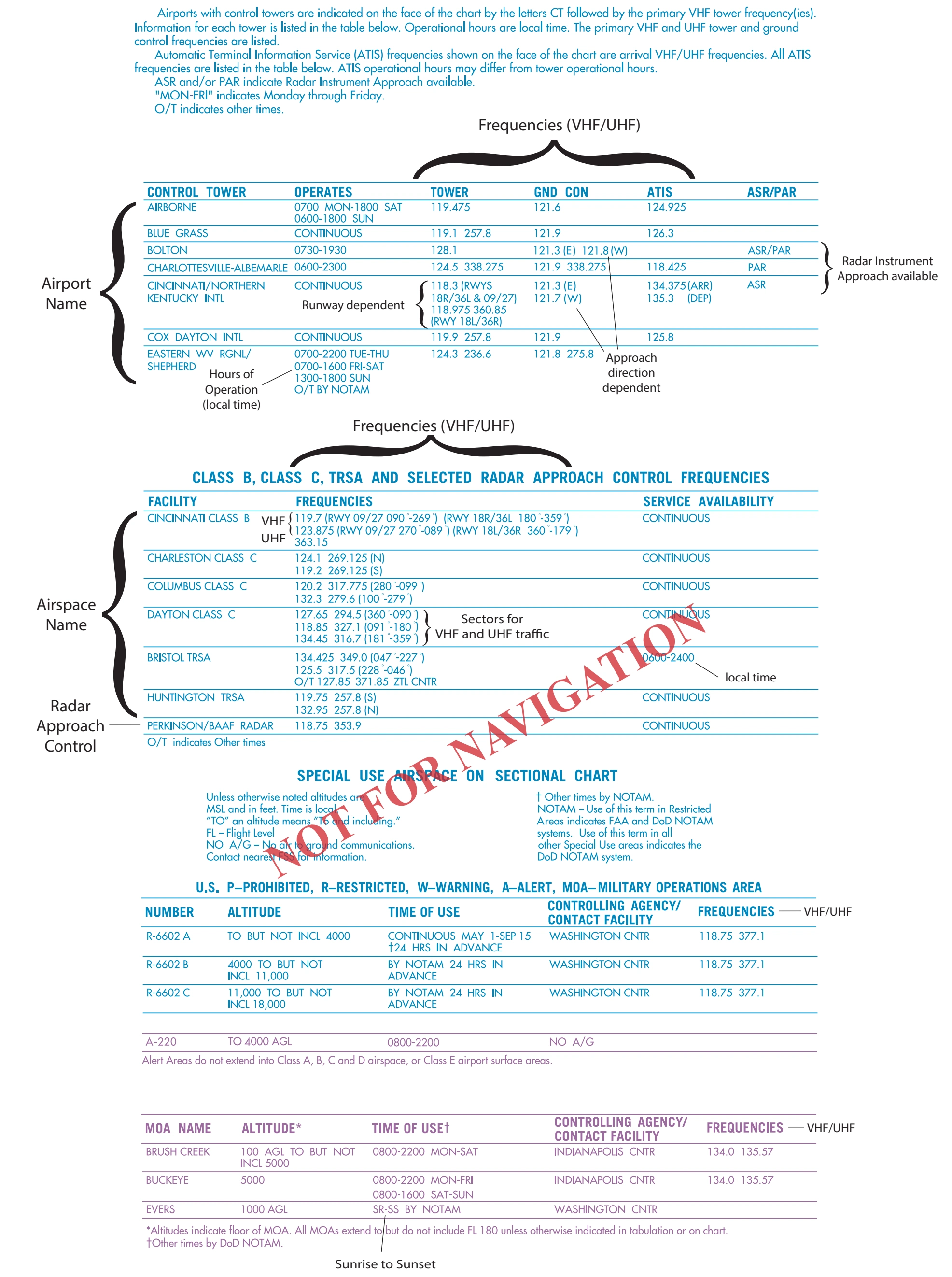
TERMINAL AREA CHART (TAC) COVERAGE TAC coverage is shown on appropriate Sectionals by a 1/4" masked line as indicated below. Within this area pilots should use TACs, which provide greater detail. A note indicating that the area is on the TAC appears near the masked boundary line. INSET AND SPECIAL CHART COVERAGE Inset and Special Chart Coverage (.i.e., Grand Canyon Chart) is shown on appropriate Sectionals by a 1/8" masked line as indicated below. A note to this effect appears near the masked boundary line. (Additional examples shown in VFR Sectional and Terminal Charts > Navigational and Procedural Information > Chart Limits.) CHART TABULATIONS Airport Tower Communications are provided in a columnized tabulation for all tower-controlled airports that appear on the respective chart. Airport names are listed alphabetically. If the airport is military, the type of airfield, e.g., AAF, AFB, NAS, is shown after the airfield name. In addition to the airport name, tower operating hours, primary Very High Frequency/Ultra High Frequency (VHF/UHF) local Control Tower (CT), Ground Control (GND CON), and Automatic Terminal Information Service (ATIS) frequencies, when available, will be given. Airport Surveillance Radar (ASR) and/or Precision Approach Radar (PAR) procedures are listed when available. Approach Control Communications are provided in a columnized tabulation listing Class B, Class C, Terminal Radar Service Areas (TRSA) and Selected Approach Control Facilities when available. Primary VHF/UHF frequencies are provided for each facility. Sectorization occurs when more than one frequency exists and/or is approach direction dependent. Availability of service hours is also provided. Special Use Airspace (SUA): Prohibited, Restricted and Warning Areas are presented in blue and listed numerically for U.S. and other countries. A tabulation of Alert Areas (listed numerically) and Military Operations Areas (MOA) (listed alphabetically) appear on the chart in magenta. All are supplemented with altitude, time of use and the controlling agency/ contact facility, and its frequency when available. Users need to be aware that a NOTAM addressing activation will NOT be issued to announce permanently listed times of use. The controlling agency will be shown when the contact facility and frequency data is unavailable. FAA Chart Users Guide - VFR Terms and Symbols
Source page 21
Chart-tabulations sample page — source page 21.
Cookie Preferences
We use cookies to operate this website, improve performance, understand site traffic, and personalize your experience. Essential cookies are always active because they are required for the website to function.
Required for basic site functionality and security.
Help us understand how visitors use the website so we can improve it.
May be used for advertising, remarketing, or social media features.
You can update your choices anytime using Cookie Settings. View Privacy Policy