Searchable explanations of VFR chart terrain, water, obstructions, radio aids, airports, airspace, foreign areas, and chart coverage.
The symbol indicates the existence of a rotating or flashing airport beacon operating from dusk to dawn. The Aeronautical Information Manual (AIM) thoroughly explains the types and uses of airport lighting aids.
Rotating or flashing airport beacon operating from dusk to dawn — source page 15.
Airports are plotted in their true geographic position unless the symbol conflicts with a NAVAID at the same location. In such cases, the airport symbol will be displaced, but the relationship between the airport and the NAVAID will be retained. When a waypoint is collocated with a towered airport, the waypoint symbol will not be charted and the waypoint name followed by (WP) will be shown leadered to the waypoint true location. When depicting a seaplane base, the eye of the anchor symbol will be charted as close to the docking area as possible, with the remainder of the symbol in the water. Airports are identified by their official FAA designated name. UNICOM The elevation of an airport is the highest point on the usable portion of the landing areas. Runway length is the length of the longest active runway, including displaced thresholds and excluding overruns. Runway length is shown to the nearest 100', using 70 as the rounding point; a runway 8070' in length is charted as 81, while a runway 8069' in length is charted as 80. If an airport has waterways, it will be indicated by a seaplane base symbol and additional elevation, lighting, and length information under primary airport information. Flight Service Station on field Elevation in feet Airports where fixed wing special VFR operations are prohibited (shown above airport name) FAR 91 Lighting in operation Sunset to Sunrise Indicates FAR 93 Special Air Traffic Rules and Airport Traffic Pattern Lighting limitations exist; refer to Chart Supplement Location Identifier Length of longest runway in hundreds of feet; usable length may be less ICAO Location Identifier Aeronautical advisory station Control Tower (CT) - primary frequency Runways with Right Traffic Patterns (public use) Star indicates operation part-time. See tower frequencies tabulation for hours of operation See Chart Supplement Follows the Common Traffic Advisory Frequency (CTAF) VFR Advisory Service Shown when ATIS is not available and frequency is other than the primary CT frequency Automatic Terminal Information Services Weather Camera Automatic Flight Information Service Airport of Entry Automated Surface Weather Observing Systems; shown when full-time ATIS is not available When information is lacking, the respective character is replaced by a dash. Lighting codes refer to runway edge lights and may not represent the longest runway or full length lighting. Airports with Control Towers (CT) and their related data are shown in blue. All other airports and their related data are shown in magenta. The symbol indicates that runway lights are on from dusk to dawn. indicates that the pilot must consult the Chart Supplement to determine runway lighting limitations, such as: available on request (by radio-call, letter, phone, etc), part-time lighting, or pilot/airport controlled lighting. Lighting codes refer to runway edge lights. The lighted runway may not be the longest runway available, and lights may not be illuminated along the full length of the runway. The Chart Supplement has a detailed description of airport and air navigation lighting aids for each airport. A dash represents no runway edge lights. The symbol indicates the existence of a rotating or flashing airport beacon operating from dusk to dawn. The Aeronautical Information Manual (AIM) thoroughly explains the types and uses of airport lighting aids.
Source page 16
Right traffic information is shown using the abbreviation 'RP' for right pattern, followed by the appropriate runway number(s) (RP 18). Special conditions or restrictions to the right pattern are indicated by the use of an asterisk (*RP) to direct the pilot to the Chart Supplement for special instructions and/or restrictions.
The type “OBJECTIONABLE” associated with an airport symbol indicates that an objectionable airspace determination has been made for the airport per FAA JO 7400.2 Section 4, Airport Charting and Publication of Airport Data. Objectionable airspace determinations are based upon a number of factors including conflicting traffic patterns with another airport, hazardous runway conditions, or natural or man-made obstacles in close proximity to the landing area. FAA Regional Airports Offices are responsible for airspace determinations. Address any challenges to objectionable airspace determinations to your FAA Regional Airports Office.
AIRSPACE
CONTROLLED AIRSPACE
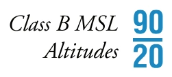
Class B altitude notation — ceiling 9,000 ft MSL / floor 2,000 ft MSL — source page 16.
Class B airspace name — LAS VEGAS CLASS B — source page 16.
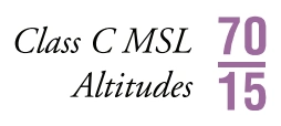
Class C altitude notation — ceiling 7,000 ft MSL / floor 1,500 ft MSL — source page 16.
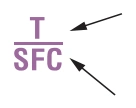
| A ceiling value of “T” indicates the ceiling is to, but not including, the floor of the overlying Class B airspace. Surface.
Class C T/SFC altitude notation — ceiling to overlying Class B floor / surface floor — source page 16.
Class C airspace name — BURBANK CLASS C — source page 16.
Class C approach-control frequency box — CTC BURBANK APP within 20 NM on 124.6/395.9 — source page 16.
Class C effective-hours note — see NOTAMs/Supplement — source page 16.
See NOTAMs or Chart Supplement for Class D effective hours — source page 16.
Class D airspace ceiling — 3,000 ft MSL example — source page 16.
Right traffic information is shown using the abbreviation 'RP' for right pattern, followed by the appropriate runway number(s) (RP 18). Special conditions or restrictions to the right pattern are indicated by the use of an asterisk (*RP) to direct the pilot to the Chart Supplement for special instructions and/or restrictions. The type “OBJECTIONABLE” associated with an airport symbol indicates that an objectionable airspace determination has been made for the airport per FAA JO 7400.2 Section 4, Airport Charting and Publication of Airport Data. Objectionable airspace determinations are based upon a number of factors including conflicting traffic patterns with another airport, hazardous runway conditions, or natural or man-made obstacles in close proximity to the landing area. FAA Regional Airports Offices are responsible for airspace determinations. Address any challenges to objectionable airspace determinations to your FAA Regional Airports Office. AIRSPACE CONTROLLED AIRSPACE Controlled airspace consists of those areas where some or all aircraft may be subject to air traffic control, such as: Class A, Class B, Class C, Class D, Class E Surface (SFC) and Class E Airspace. Class A Airspace within the United States extends from 18,000' up to FL600. While visual charts do not depict Class A, it is important to note its existence. Class B Airspace is shown on the Sectional Aeronautical Chart (Sectional) and Terminal Area Chart (TAC). The MSL ceiling and floor altitudes of each sector are shown in solid blue figures with the last two zeros omitted. Floors extending "upward from above" a certain altitude are preceded by a (+). Operations at and below these altitudes are outside of Class B Airspace. Radials and arcs used to define Class B are prominently shown on TACs. Detailed rules and requirements associated with the particular Class B are shown. The name by which the Class B is shown as for example. Class C Airspace is shown on Sectionals and TACs. The MSL ceiling and floor altitudes of each sector are shown in solid magenta figures with the last two zeros eliminated. A ceiling value of “T” indicates the ceiling is to, but not including, the floor of the overlying Class B airspace. Surface. Class C Airspace is identified by name: Separate notes, enclosed in magenta boxes, give the approach control frequencies to be used by arriving VFR aircraft to establish two-way radio communication before entering the Class C (generally within 20 NM): Class C operating less than continuous is indicated by the following note: Class D Airspace is identified with a blue dashed line. Class D operating less than continuous is indicated by the following note: Ceilings of Class D are shown as follows: A minus in front of the figure is used to indicate "from surface to, but not including..." FAA Chart Users Guide - VFR Terms and Symbols
Source page 17
Cookie Preferences
We use cookies to operate this website, improve performance, understand site traffic, and personalize your experience. Essential cookies are always active because they are required for the website to function.
Required for basic site functionality and security.
Help us understand how visitors use the website so we can improve it.
May be used for advertising, remarketing, or social media features.
You can update your choices anytime using Cookie Settings. View Privacy Policy