
Chapter 1
Aircraft Structures
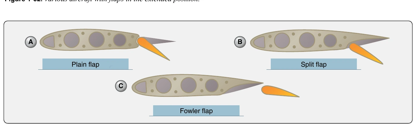
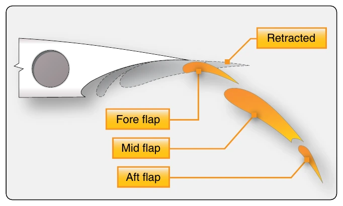
An enhanced version of the Fowler flap is a set of flaps that actually contains more than one aerodynamic surface. Figure 1-64 shows a triple-slotted flap. In this configuration, the flap consists of a fore flap, a mid flap, and an aft flap. When deployed, each flap section slides aft on tracks as it lowers. The flap sections also separate leaving an open slot between the wing and the fore flap, as well as between each of the flap sections. Air from the underside of the wing flows through these slots. The result is that the laminar flow on the upper surfaces is enhanced. The greater camber and effective wing area increase overall lift.
Heavy aircraft often have leading edge flaps that are used in conjunction with the trailing edge flaps. [Figure 1-65] They can be made of machined magnesium or can have an aluminum or composite structure. While they are not installed or operate independently, their use with trailing edge flaps can greatly increase wing camber and lift. When stowed, leading edge flaps retract into the leading edge of the wing.
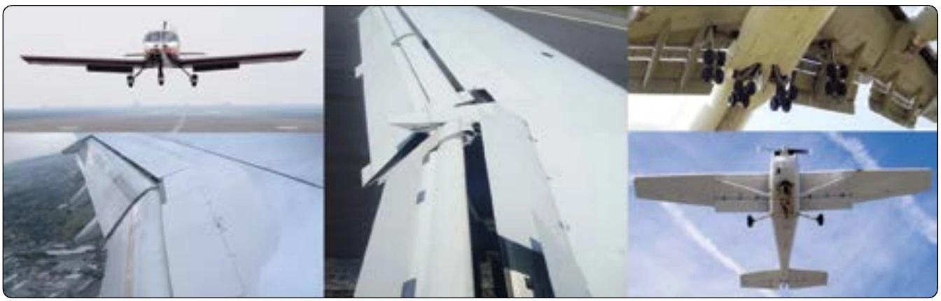
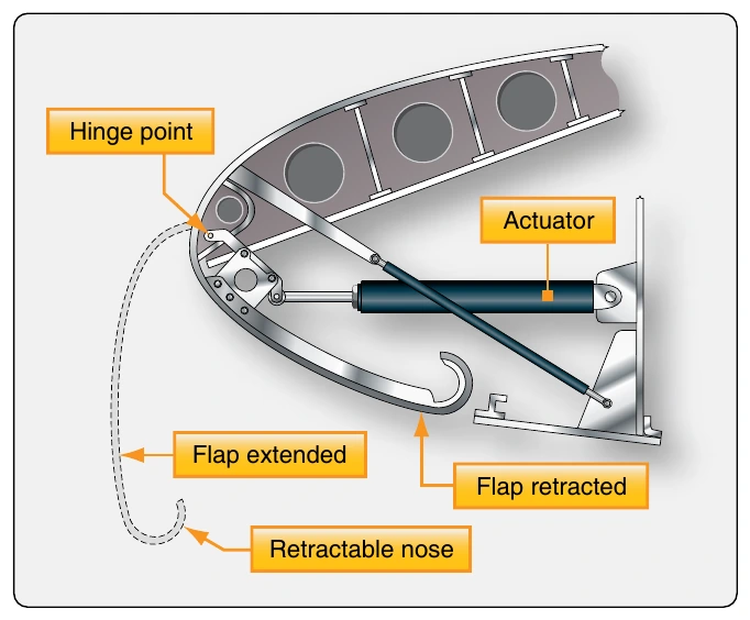
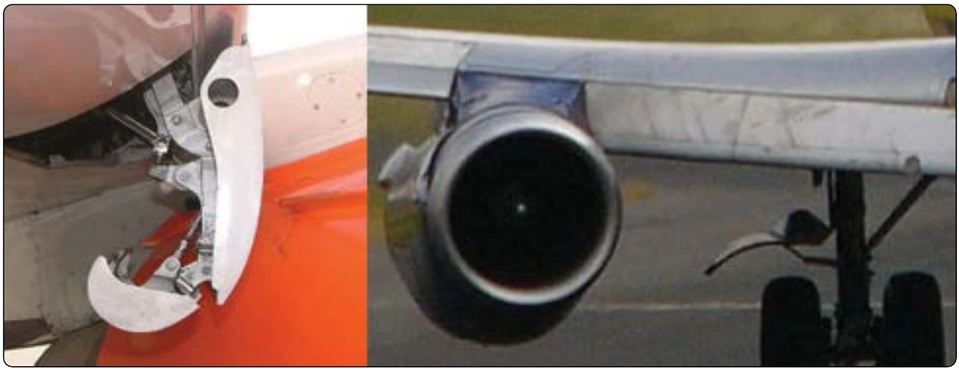
The differing designs of leading edge flaps essentially provide the same effect. Activation of the trailing edge flaps automatically deploys the leading edge flaps, which are driven out of the leading edge and downward, extending the camber of the wing. Figure 1-66 shows a Krueger flap, recognizable by its flat mid-section.
Slats
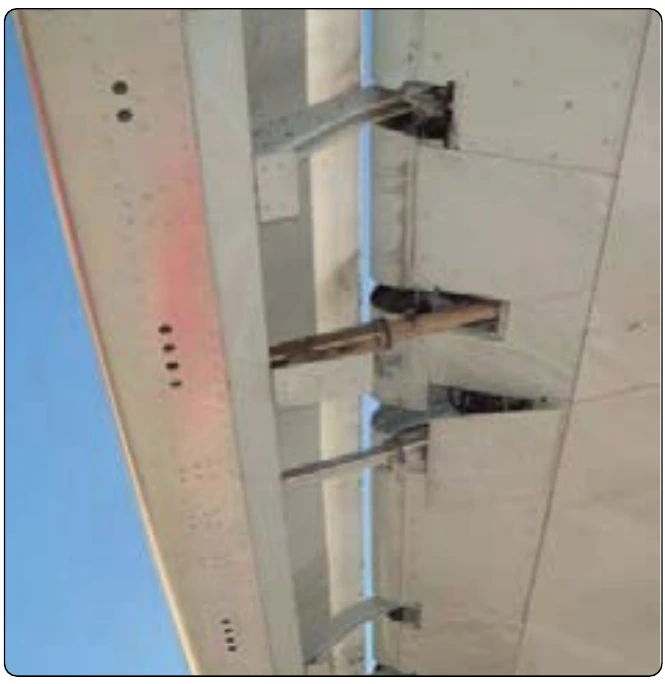
Another leading edge device which extends wing camber is a slat. Slats can be operated independently of the flaps with their own switch in the flight deck. Slats not only extend out of the leading edge of the wing increasing camber and lift, but most often, when fully deployed leave a slot between their trailing edges and the leading edge of the wing. [Figure 1-67] This increases the angle of attack at which the wing will maintain its laminar airflow, resulting in the ability to fly the aircraft slower with a reduced stall speed, and still maintain control.
Spoilers & Speed Brakes
A spoiler is a device found on the upper surface of many heavy and high-performance aircraft. It is stowed flush to the wing’s upper surface. When deployed, it raises up into the airstream and disrupts the laminar airflow of the wing, thus reducing lift.
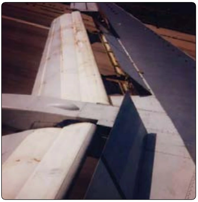
Spoilers are made with similar construction materials and techniques as the other flight control surfaces on the aircraft. Often, they are honeycomb-core flat panels. At low speeds, spoilers are rigged to operate when the ailerons operate to assist with the lateral movement and stability of the aircraft. On the wing where the aileron is moved up, the spoilers also raise thus amplifying the reduction of lift on that wing. [Figure 1-68] On the wing with downward aileron deflection, the spoilers remain stowed. As the speed of the aircraft increases, the ailerons become more effective and the spoiler interconnect disengages.
Spoilers are unique in that they may also be fully deployed on both wings to act as speed brakes. The reduced lift and increased drag can quickly reduce the speed of the aircraft in flight. Dedicated speed brake panels similar to flight spoilers in construction can also be found on the upper surface of the wings of heavy and high-performance aircraft. They are designed specifically to increase drag and reduce the speed of the aircraft when deployed. These speed brake panels do not operate differentially with the ailerons at low speed. The speed brake control in the flight deck can deploy all spoiler and speed brake surfaces fully when operated. Often, these surfaces are also rigged to deploy on the ground automatically when engine thrust reversers are activated.
Tabs
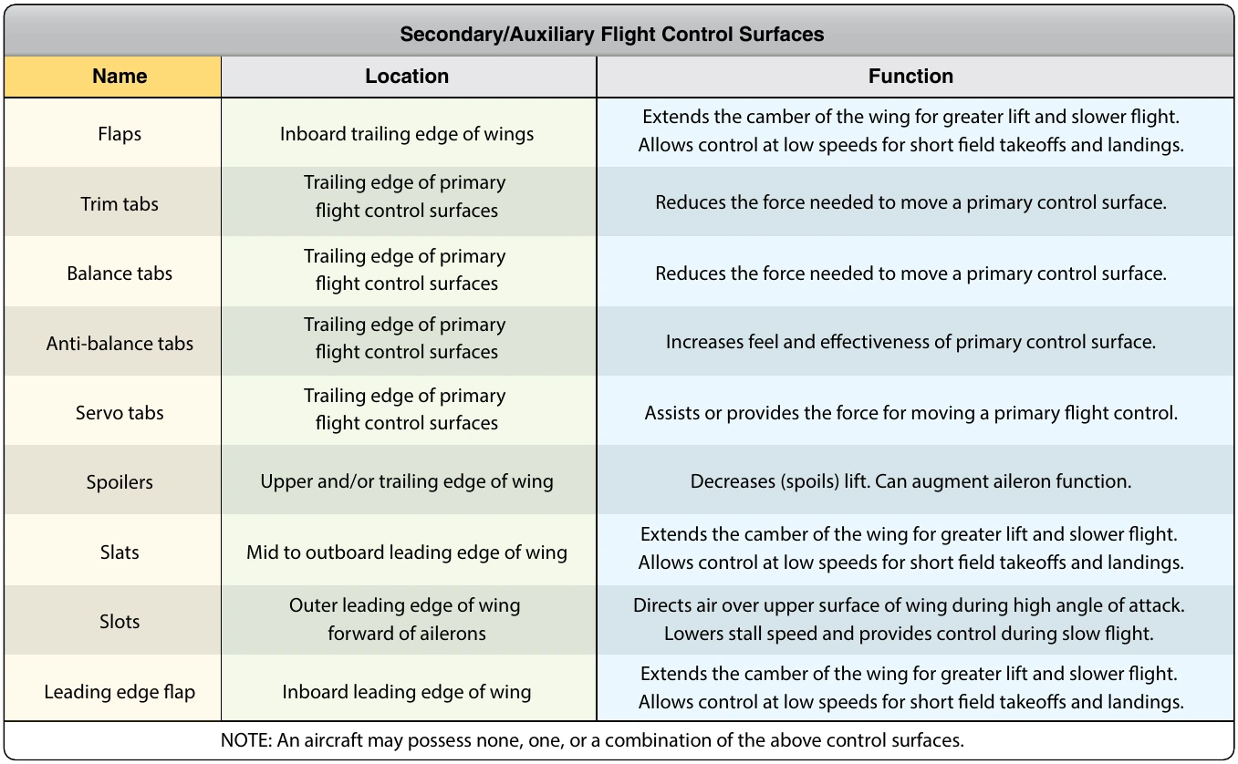
The force of the air against a control surface during the high speed of flight can make it difficult to move and hold that control surface in the deflected position. A control surface might also be too sensitive for similar reasons. Several different tabs are used to aid with these types of problems. The table in Figure 1-69 summarizes the various tabs and their uses.
While in flight, it is desirable for the pilot to be able to take their hands and feet off of the controls and have the aircraft maintain its flight condition. Trims tabs are designed to allow this. Most trim tabs are small movable surfaces located on the trailing edge of a primary flight control surface. A small movement of the tab in the direction opposite of the direction the flight control surface is deflected, causing air to strike the tab, in turn producing a force that aids in maintaining the flight control surface in the desired position. Through linkage set from the flight deck, the tab can be positioned so that it is actually holding the control surface in position rather than the pilot. Therefore, elevator tabs are used to maintain the speed of the aircraft since they assist in maintaining the selected pitch. Rudder tabs can be set to hold yaw in check and maintain heading. Aileron tabs can help keep the wings level.