Chapter 1
Aircraft Structures
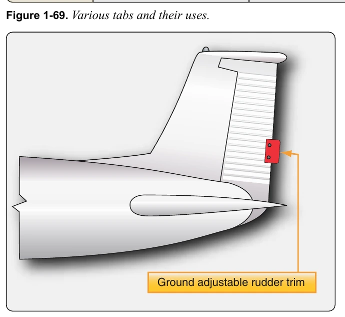
Occasionally, a simple light aircraft may have a stationary metal plate attached to the trailing edge of a primary flight control, usually the rudder. This is also a trim tab as shown in
aircraft in flight to a hands-off condition when flying straight and level. The correct amount of bend can be determined only by flying the aircraft after an adjustment. Note that a small amount of bending is usually sufficient.
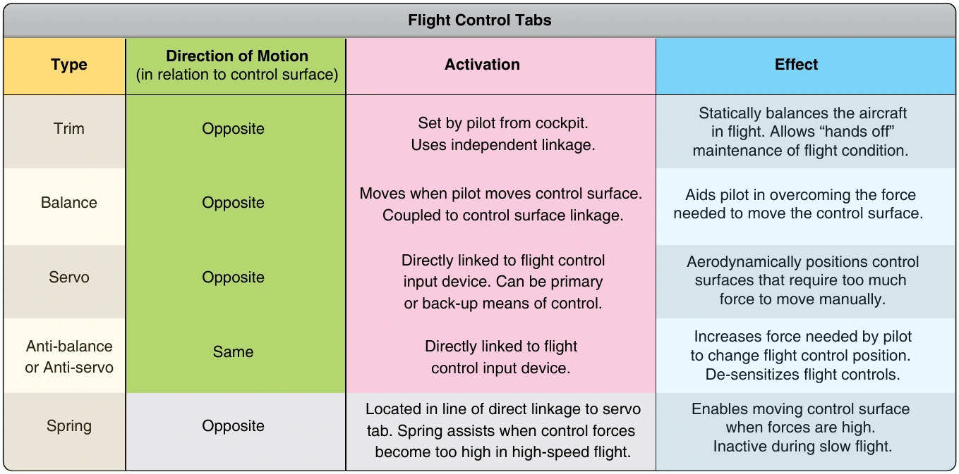
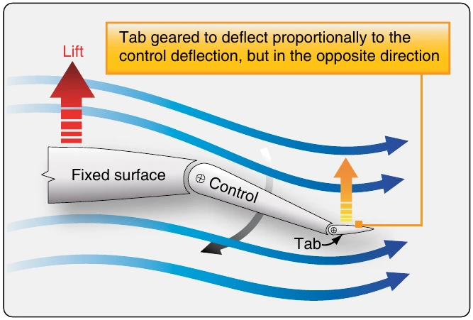
The aerodynamic phenomenon of moving a trim tab in one direction to cause the control surface to experience a force moving in the opposite direction is exactly what occurs with the use of balance tabs. [Figure 1-71] Often, it is difficult to move a primary control surface due to its surface area and the speed of the air rushing over it. Deflecting a balance tab hinged at the trailing edge of the control surface in the opposite direction of the desired control surface movement causes a force to position the surface in the proper direction with reduced force to do so. Balance tabs are usually linked directly to the control surface linkage so that they move automatically when there is an input for control surface movement. They also can double as trim tabs, if adjustable in the flight deck.
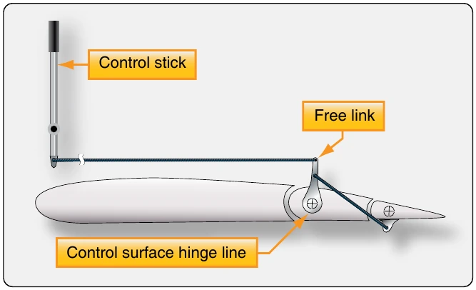
A servo tab is similar to a balance tab in location and effect, but it is designed to operate the primary flight control surface, not just reduce the force needed to do so. It is usually used as a means to back up the primary control of the flight control surfaces. [Figure 1-72]
On heavy aircraft, large control surfaces require too much force to be moved manually and are usually deflected out of the neutral position by hydraulic actuators. These power control units are signaled via a system of hydraulic valves connected to the yoke and rudder pedals. On fly-by-wire aircraft, the hydraulic actuators that move the flight control surfaces are signaled by electric input. In the case of hydraulic system failure(s), manual linkage to a servo tab can be used to deflect it. This, in turn, provides an aerodynamic force that moves the primary control surface.
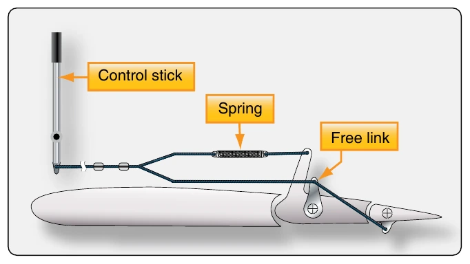
A control surface may require excessive force to move only in the final stages of travel. When this is the case, a spring tab can be used. This is essentially a servo tab that does not activate until an effort is made to move the control surface beyond a certain point. When reached, a spring in line of the control linkage aids in moving the control surface through the remainder of its travel. [Figure 1-73]
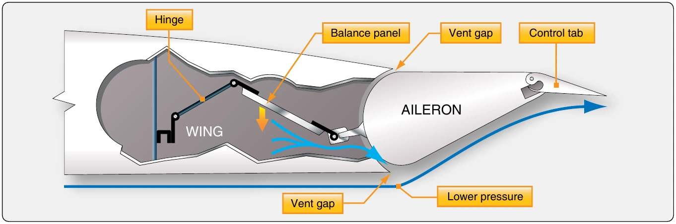
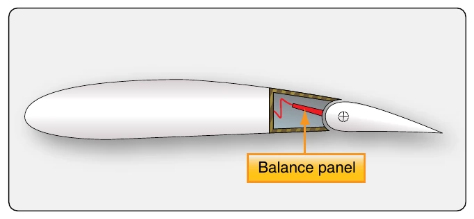
Figure 1-74 shows another way of assisting the movement of an aileron on a large aircraft. It is called an aileron balance panel. Not visible when approaching the aircraft, it is positioned in the linkage that hinges the aileron to the wing.
Balance panels have been constructed typically of aluminum skin-covered frame assemblies or aluminum honeycomb structures. The trailing edge of the wing just forward of the leading edge of the aileron is sealed to allow controlled airflow in and out of the hinge area where the balance panel is located. [Figure 1-75] When the aileron is moved from the neutral position, differential pressure builds up on one side of the balance panel. This differential pressure acts on the balance panel in a direction that assists the aileron movement. For slight movements, deflecting the control tab at the trailing edge of the aileron is easy enough to not require significant assistance from the balance tab. (Moving the control tab moves the ailerons as desired.) But, as greater deflection is requested, the force resisting control tab and aileron movement becomes greater and augmentation from the balance tab is needed. The seals and mounting geometry allow the differential pressure of airflow on the balance panel to increase as deflection of the ailerons is increased. This makes the resistance felt when moving the aileron controls relatively constant.
Antiservo tabs, as the name suggests, are like servo tabs but move in the same direction as the primary control surface. On some aircraft, especially those with a movable horizontal stabilizer, the input to the control surface can be too sensitive. An antiservo tab tied through the control linkage creates an aerodynamic force that increases the effort needed to move the control surface. This makes flying the aircraft more stable for the pilot. Figure 1-76 shows an antiservo tab in the near neutral position. Deflected in the same direction as the desired stabilator movement, it increases the required control surface input.
Other Wing Features
There may be other structures visible on the wings of an aircraft that contribute to performance. Winglets, vortex generators, stall fences, and gap seals are all common wing features. Introductory descriptions of each are given in the following paragraphs.
A winglet is an obvious vertical upturn of the wing’s tip resembling a vertical stabilizer. It is an aerodynamic device designed to reduce the drag created by wing tip vortices in flight. Usually made from aluminum or composite materials, winglets can be designed to optimize performance at a desired speed. [Figure 1-77]
Vortex generators are small airfoil sections usually attached to the upper surface of a wing. [Figure 1-78] They are designed to promote smooth, or non-turbulent, airflow over the wing and control surfaces. Usually made of aluminum and installed in a spanwise line or lines, the vortices created by these devices swirl downward assisting maintenance of the boundary layer of air flowing over the wing. They can also be found on the fuselage and empennage. Figure 1-79 shows the unique vortex generators on a Symphony SA-160 wing.