Chapter 1
Aircraft Structures
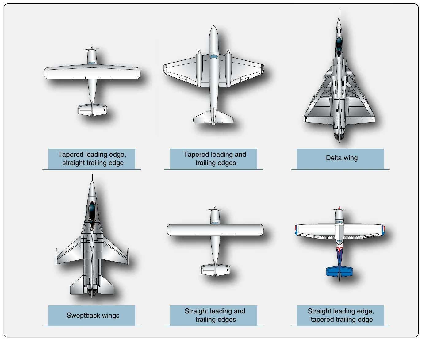
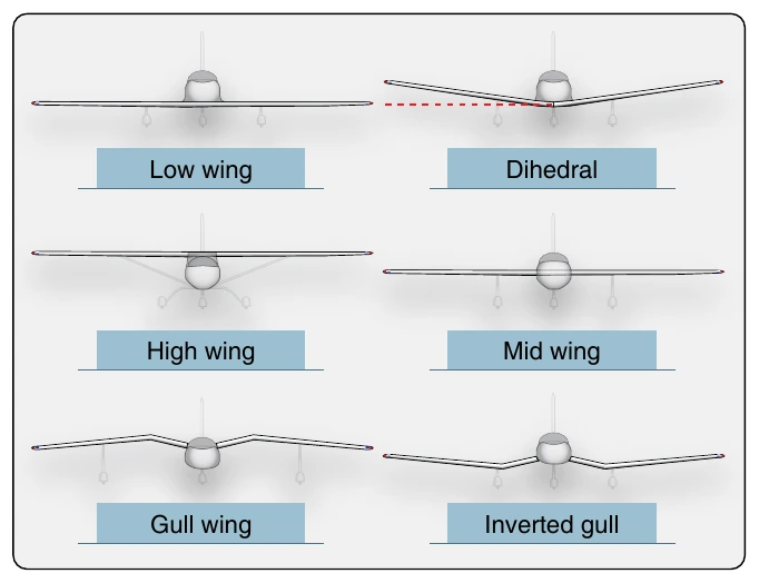
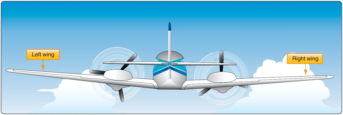
The wings of an aircraft are designed to lift it into the air. Their particular design for any given aircraft depends on a number of factors, such as size, weight, use of the aircraft, desired speed in flight and at landing, and desired rate of climb. The wings of aircraft are designated left and right, corresponding to the left and right sides of the operator when seated in the flight deck. [Figure 1-21]
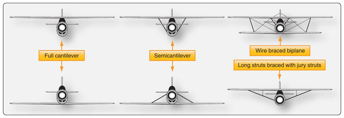
Often wings are of full cantilever design. This means they are built so that no external bracing is needed. They are supported internally by structural members assisted by the skin of the aircraft. Other aircraft wings use external struts or wires to assist in supporting the wing and carrying the aerodynamic and landing loads. Wing support cables and struts are generally made from steel. Many struts and their attach fittings have fairings to reduce drag. Short, nearly vertical supports called jury struts are found on struts that attach to the wings a great distance from the fuselage. This serves to subdue strut movement and oscillation caused by the air flowing around the strut in flight. Figure 1-22 shows samples of wings using external bracing, also known as semicantilever wings. Cantilever wings built with no external bracing are also shown.
Aluminum is the most common material from which to construct wings, but they can be wood covered with fabric, and occasionally a magnesium alloy has been used. Moreover, modern aircraft are tending toward lighter and stronger materials throughout the airframe and in wing construction. Wings made entirely of carbon fiber or other composite materials exist, as well as wings made of a combination of materials for maximum strength to weight performance.
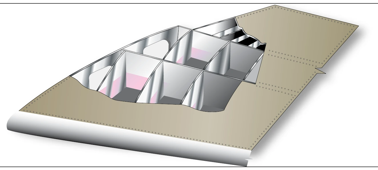
The internal structures of most wings are made up of spars and stringers running spanwise and ribs and formers or bulkheads running chordwise (leading edge to trailing edge). The spars are the principle structural members of a wing. They support all distributed loads, as well as concentrated weights such as the fuselage, landing gear, and engines. The skin, which is attached to the wing structure, carries part of the loads imposed during flight. It also transfers the stresses to the wing ribs. The ribs, in turn, transfer the loads to the wing spars. [Figure 1-23] In general, wing construction is based on one of three fundamental designs:
- Monospar
- Multispar
- Box beam
Modification of these basic designs may be adopted by various manufacturers.
The monospar wing incorporates only one main spanwise or longitudinal member in its construction. Ribs or bulkheads supply the necessary contour or shape to the airfoil. Although the strict monospar wing is not common, this type of design modified by the addition of false spars or light shear webs along the trailing edge for support of control surfaces is sometimes used.
The multispar wing incorporates more than one main longitudinal member in its construction. To give the wing contour, ribs or bulkheads are often included.
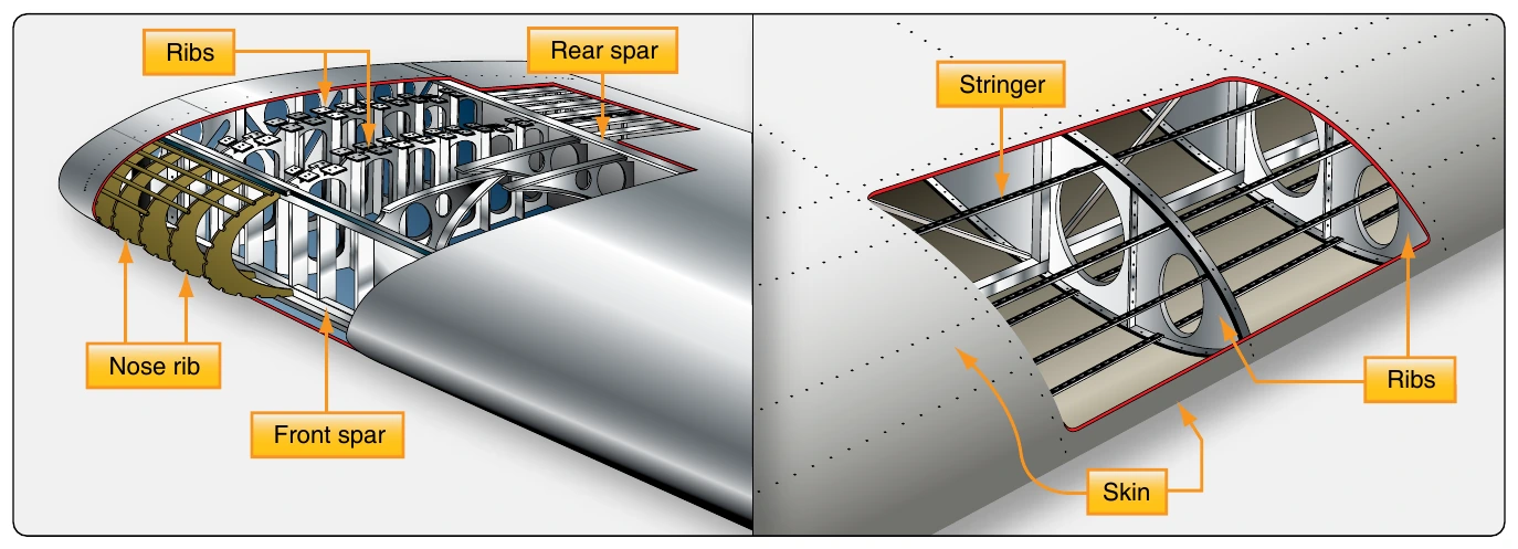
The box beam type of wing construction uses two main longitudinal members with connecting bulkheads to furnish additional strength and to give contour to the wing. [Figure 1-24] A corrugated sheet may be placed between the bulkheads and the smooth outer skin so that the wing can better carry tension and compression loads. In some cases, heavy longitudinal stiffeners are substituted for the upper surface of the wing and stiffeners on the lower surface corrugated sheets. A combination of corrugated sheets on the upper surface of the wing and stiffeners on the lower surface is sometimes used. Air transport category aircraft often utilize box beam wing construction.
Wing Spars
Spars are the principal structural members of the wing. They correspond to the longerons of the fusel age. They run parallel to the lateral axis of the aircraft, from the fuselage toward the tip of the wing, and are usually attached to the fuselage by wing fittings, plain beams, or a truss.
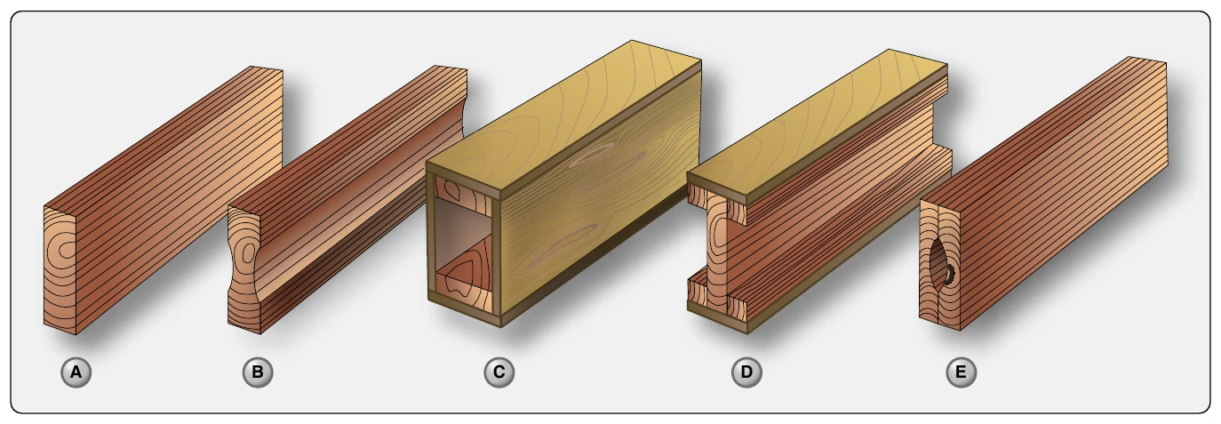
Spars may be made of metal, wood, or composite materials depending on the design criteria of a specific aircraft. Wooden spars are usually made from spruce. They can be generally classified into four different types by their cross-sectional configur ation. As shown in Figure 1-25, they may be (A) solid, (B) box-shaped, (C) partly hollow, or (D) in the form of an I-beam. Lamination of solid wood spars is often used to increase strength. Laminated wood can also be found in box-shaped spars. The spar in Figure 1-25E has had material removed to reduce weight but retains the strength of a rectangular spar. As can be seen, most wing spars are basically rectangular in shape with the long dimension of the cross-section oriented up and down in the wing.
Currently, most manufactured aircraft have wing spars made of solid extruded aluminum or aluminum extrusions riveted together to form the spar. The increased use of composites and the combining of materials should make airmen vigilant for wings spars made from a variety of materials. Figure 1-26 shows examples of metal wing spar cross-sections.