
Chapter 10
Aircraft Systems
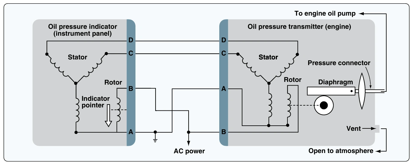
Aircraft with digital instrumentation make use of pressure-sensitive solid-state sensors that output digital signals for collection and processing by dedicated engine and airframe computers. Others may retain their analog sensors but may forward this information through an analog to digital converter unit from which the appropriate computer can obtain digital information to process and illuminate the digital display. Many more instruments utilize the synchro remote-indicating systems described in this section or similar synchros. Sometimes simple, more suitable, or less expensive technologies are also employed.
Mechanical Movement Indicators
There are many instruments on an aircraft that indicate the mechanical motion of a component, or even the aircraft itself. Some utilize the synchro remote-sensing and indicating systems described above. Other means for capturing and displaying mechanical movement information are also used. This section discusses some unique mechanical motion indicators and groups instruments by function. All give valuable feedback to the pilot on the condition of the aircraft in flight.
Tachometers
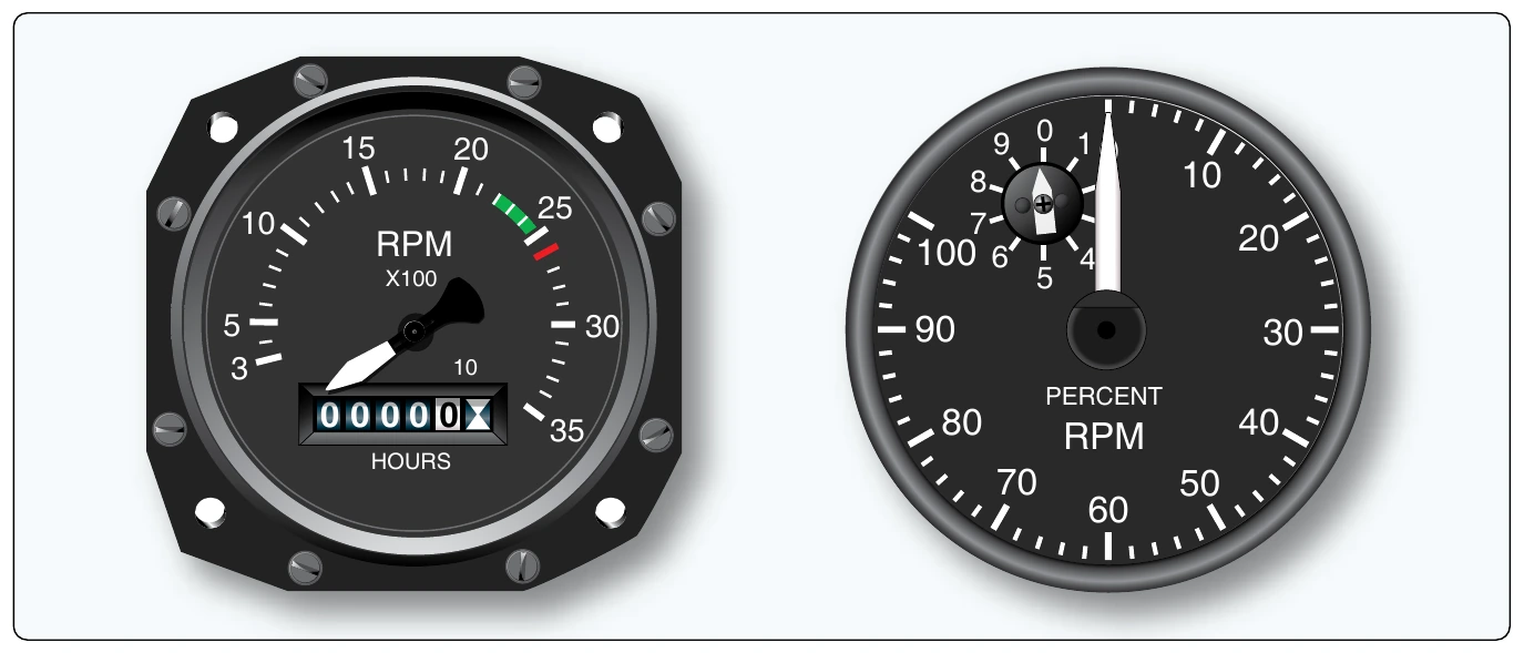
The tachometer, or tach, is an instrument that indicates the speed of the crankshaft of a reciprocating engine. It can be a direct- or remote-indicating instrument, the dial of which is calibrated to indicate revolutions per minutes (rpm). On reciprocating engines, the tach is used to monitor engine power and to ensure the engine is operated within certified limits.
Gas turbine engines also have tachometers. They are used to monitor the speed(s) of the compressor section(s) of the engine. Turbine engine tachometers are calibrated in percentage of rpm with 100 percent corresponding to optimum turbine speed. This allows similar operating procedures despite the varied actual engine rpm of different engines. [Figure 10-52]
In addition to the engine tachometer, helicopters use a tachometer to indicator main rotor shaft rpm. It should also be noted that many reciprocating-engine tachometers also have built-in numeric drums that are geared to the rotational mechanism inside. These are hour meters that keep track of the time the engine is operated. There are two types of tachometer system in wide use today: mechanical and electrical.
Mechanical Tachometers
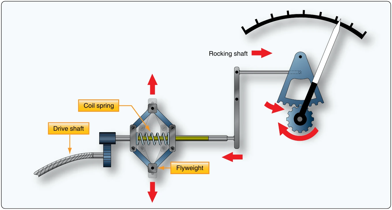
Mechanical tachometer indicating systems are found on small, single-engine light aircraft in which a short distance exists between the engine and the instrument panel. They consist of an indicator connected to the engine by a flexible drive shaft. The drive shaft is geared into the engine so that when the engine turns, so does the shaft. The indicator contains a flyweight assembly coupled to a gear mechanism that drives a pointer. As the drive shaft rotates, centrifugal force acts on the flyweights and moves them to an angular position. This angular position varies with the rpm of the engine. The amount of movement of the flyweights is transmitted through the gear mechanism to the pointer. The pointer rotates to indicate this movement on the tachometer indicator, which is directly related to the rpm of the engine. [Figure 10-53]
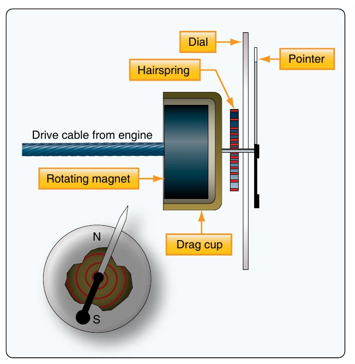
A more common variation of this type of mechanical tachometer uses a magnetic drag cup to move the pointer in the indicator. As the drive shaft turns, it rotates a permanent magnet in a close-tolerance aluminum cup. A shaft attached to the indicating point is attached to the exterior center of the cup. As the magnet is rotated by the engine flex drive cable, its magnetic field cuts through the conductor surrounding it, creating eddy currents in the aluminum cup. This current flow creates its own magnetic field, which interacts with the rotating magnet’s flux field. The result is that the cup tends to rotate, and with it, the indicating pointer. A calibrated restraining spring limits the cup’s rotation to the arc of motion of the pointer across the scale on the instrument face. [Figure 10-54]
Electric Tachometers
It is not practical to use a mechanical linkage between the engine and the rpm indicator on aircraft with engines not mounted in the fuselage just forward of the instrument panel. Greater accuracy with lower maintenance is achieved through the use of electric tachometers. A wide variety of electric tachometer systems can be employed, so manufacturer’s instructions should be consulted for details of each specific tachometer system.
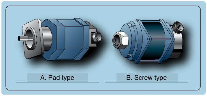
A popular electric tachometer system makes use of a small AC generator mounted to a reciprocating engine’s gear case or the accessory drive section of a turbine engine. As the engine turns, so does the generator. The frequency output of the generator is directly proportional to the speed of the engine. It is connected via wires to a synchronous motor in the indicator that mirrors this output. A drag cup, or drag disc link, is used to drive the indicator as in a mechanical tachometer. [Figure 10-55] Two different types of generator units, distinguished by their type of mounting system, are shown in Figure 10-56.
The dual tachometer consists of two tachometer indicator units housed in a single case. The indicator pointers show simultaneously, on one or two scales, the rpm of two engines. A dual tachometer on a helicopter often shows the rpm of the engine and the rpm of the main rotor. A comparison of the voltages produced by the two tach generators of this type of helicopter indicator gives information concerning clutch slippage. Athird indication showing this slippage is sometimes included in the helicopter tachometer. [Figure 10-57]
Some turbine engines use tachometer probes for rpm indication, rather than a tach generator system. They provide a great advantage in that there are no moving parts. The probes are sealed units that are mounted on a flange and protrude into the compressor section of the engine. A magnetic field is set up inside the probe that extends through pole pieces and out the end of the probe. A rotating gear wheel, which moves at the same speed as the engine compressor shaft, alters the magnetic field flux density as it moves past the pole pieces at close proximity. This generates voltage signals in coils inside the probe. The amplitude (voltage) of the signals vary directly with the speed of the engine.