
Chapter 10
Aircraft Systems
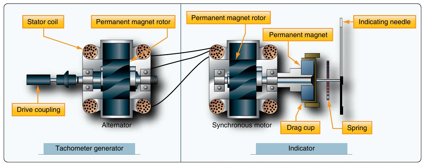
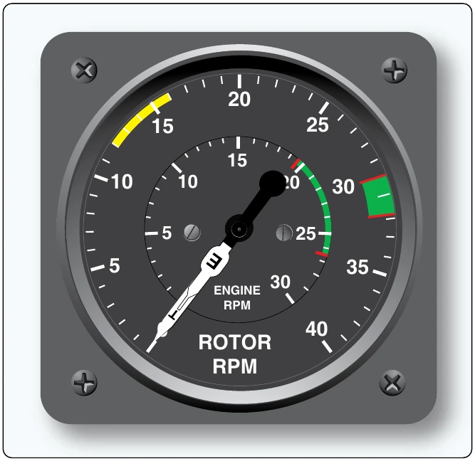
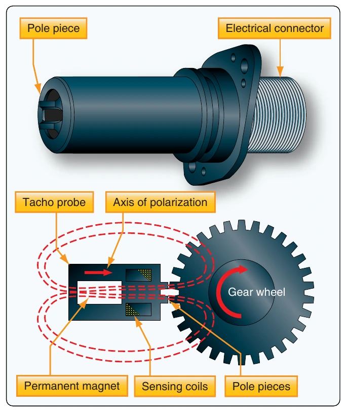
The tachometer probe’s output signals need to be processed in a remotely located module. They must also be amplified to drive a servo motor type indicator in the flight deck. They may also be used as input for an autothrottle or flight data acquisition system. [Figure 10-58]
Synchroscope
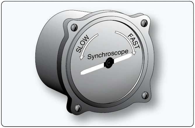
The synchroscope is an instrument that indicates whether two or more rotating devices, such as engines, are synchronized. Since synchroscopes compare rpm, they utilize the output from tachometer generators. The instrument consists of a small electric motor that receives electrical current from the generators of both engines. Current from the faster running engine controls the direction in which the synchroscope motor rotates.
If both engines are operating at exactly the same speed, the synchroscope motor does not operate. If one engine operates faster than the other, its tach generator signal causes the synchroscope motor to turn in a given direction. Should the speed of the other engine then become greater than that of the first engine, the signal from its tach generator causes the synchroscope motor to reverse itself and turn in the opposite direction. The pilot makes adjustments to steady the pointer so it does not move.
One use of synchroscope involve designating one of the engines as a master engine. The rpm of the other engine(s) is always compared to the rpm of this master engine. The dial face of the synchroscope indicator looks like Figure 10-59. “Slow” and “fast” represent the other engine’s rpm relative to the master engine, and the pilot makes adjustments accordingly.
Accelerometers
An accelerometer is an instrument that measures acceleration. It is used to monitor the forces acting upon an airframe. Accelerometers are also used in inertial reference navigation systems. The installation of accelerometers is usually limited to high-performance and aerobatic aircraft.
Simple accelerometers are mechanical, direct-reading instruments calibrated to indicate force in Gs. One G is equal to one times the force of gravity. The dial face of an accelerometer is scaled to show positive and negative forces. When an aircraft initiates a rapid climb, positive G force tends to push one back into one’s seat. Initiating a rapid decent causes a force in the opposite direction, resulting in a negative G force.
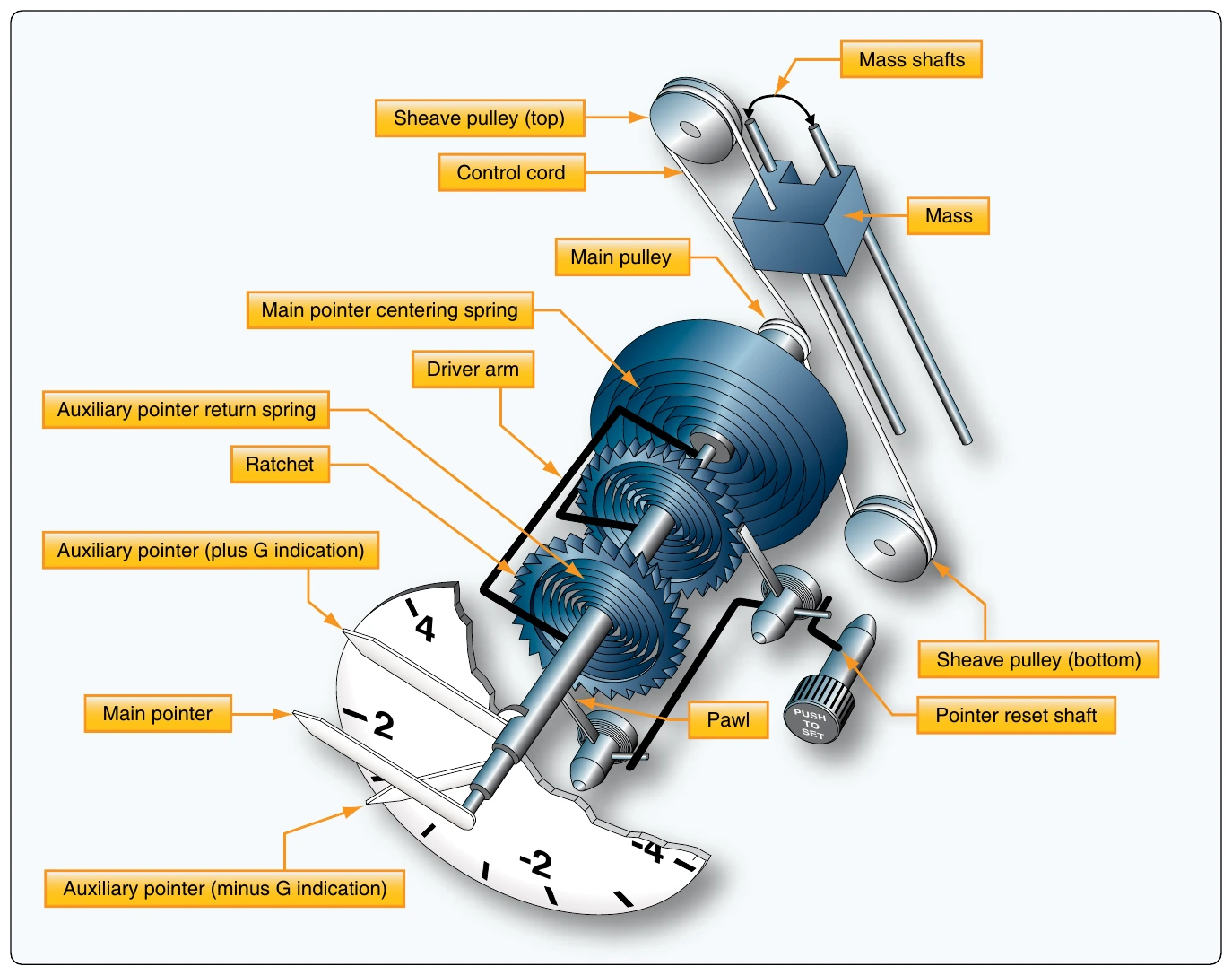
Most accelerometers have three pointers. One is continuously indicating the acceleration force experienced. The other two contain ratcheting devices. The positive G pointer follows the continuous pointer and stay at the location on the dial where the maximum positive force is indicated. The negative G pointer does the same for negative forces experienced. Both max force pointers can be reset with a knob on the instrument face.
The accelerometer operates on the principle of inertia. A mass, or weight, inside is free to slide along a shaft in response to the slightest acceleration force. When a maneuver creates an accelerating force, the aircraft and instrument move, but inertia causes the weight to stay at rest in space. As the shaft slides through the weight, the relative position of the weight on the shaft changes. This position corresponds to the force experienced. Through a series of pulleys, springs, and shafts, the pointers are moved on the dial to indicate the relative strength of the acceleration force. [Figure 10-60] Forces can act upon an airframe along the three axes of flight. Single and multi-axis accelerometers are available, although most flight deck gauges are of the single-axis type. Inertial reference navigation systems make use of multi-axis accelerometers to continuously, mathematically calculate the location of the aircraft in a three dimensional plane.
Electric and digital accelerometers also exist. Solid-state sensors are employed, such as piezoelectric crystalline devices. In these instruments, when an accelerating force is applied, the amount of resistance, current flow, or capacitance changes in direct relationship to the size of the force. Micro-electric signals integrate well with digital computers designed to process and display information in the flight deck.
Stall Warning & Angle of Attack (AOA) Indicators
An aircraft’s angle of attack (AOA) is the angle formed between the wing cord centerline and the relative wind. At a certain angle, airflow over the wing surfaces is insufficient to create enough lift to keep the aircraft flying, and a stall occurs. An instrument that monitors the AOA allows the pilot to avoid such a condition.
The simplest form of AOA indicator is a stall warning device that does not have a gauge located in the flight deck. It uses an aural tone to warn of an impending stall due to an increase in AOA. This is done by placing a reed in a cavity just aft of the leading edge of the wing. The cavity has an open passage to a precise point on the leading edge.
In flight, air flows over and under a wing. The point on the wing leading edge where the oncoming air diverges is known as the point of stagnation. As the AOA of the wing increases, the point of stagnation moves down below the open passage that leads inside the wing to the reed. Air flowing over the curved leading edge speeds up and causes a low pressure. This causes air to be sucked out of the inside of the wing through the passage. The reed vibrates as the air rushes by making a sound audible in the flight deck. [Figure 10-61] Another common device makes use of an audible tone as the AOA increases to near the point where the aircraft will stall. This stall warning device includes an electric switch that opens and closes a circuit to a warning horn audible in the flight deck. It may also be wired into a warning light circuit. The switch is located near the point of stagnation on the wing leading edge. A small lightly sprung tab activates the switch. At normal AOA, the tab is held down by air that diverges at the point of stagnation and flows under the wing. This holds the switch open so the horn does not sound nor the warning light illuminate. As the AOA increases, the point of stagnation moves down. The divergent air that flows up and over the wing now pushes the tab upward to close the switch and complete the circuit to the horn or light. [Figure 10-62]