
Chapter 10
Aircraft Systems
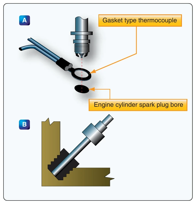
The hot junction of a thermocouple varies in shape depending on its application. Two common types are the gasket and the bayonet. In the gasket type, two rings of the dissimilar metals are pressed together to form a gasket that can be installed under a spark plug or cylinder hold down nut. In the bayonet type, the metals come together inside a perforated protective sheath. Bayonet thermocouples fit into a hole or well in a cylinder head. On turbine engines, they are found mounted on the turbine inlet or outlet case and extend through the case into the gas stream. Note that for CHT indication, the cylinder chosen for the thermocouple installation is the one that runs the hottest under most operating conditions. The location of this cylinder varies with different engines. [Figure 10-72]
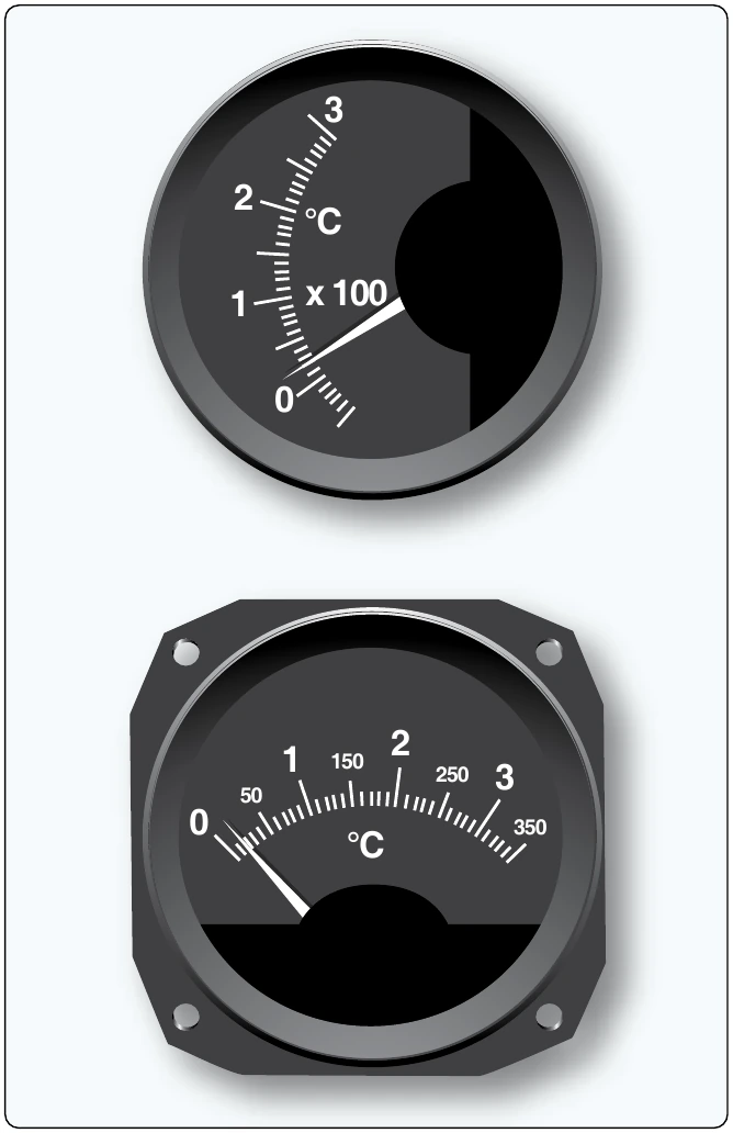
The cold junction of the thermocouple circuit is inside the instrument case. Since the electromotive force set up in the circuit varies with the difference in temperature between the hot and cold junctions, it is necessary to compensate the indicator mechanism for changes in flight deck temperature which affect the cold junction. This is accomplished by using a bimetallic spring connected to the indicator mechanism. This actually works the same as the bimetallic thermometer described previously. When the leads are disconnected from the indicator, the temperature of the flight deck area around the instrument panel can be read on the indicator dial. [Figure 10-73] Numeric LED indictors for CHT are also common in modern aircraft.
Turbine Gas Temperature Indicating Systems
EGT is a critical variable of turbine engine operation. The EGT indicating system provides a visual temperature indication in the flight deck of the turbine exhaust gases as they leave the turbine unit. In certain turbine engines, the temperature of the exhaust gases is measured at the entrance to the turbine unit. This is referred to as a turbine inlet temperature (TIT) indicating system.
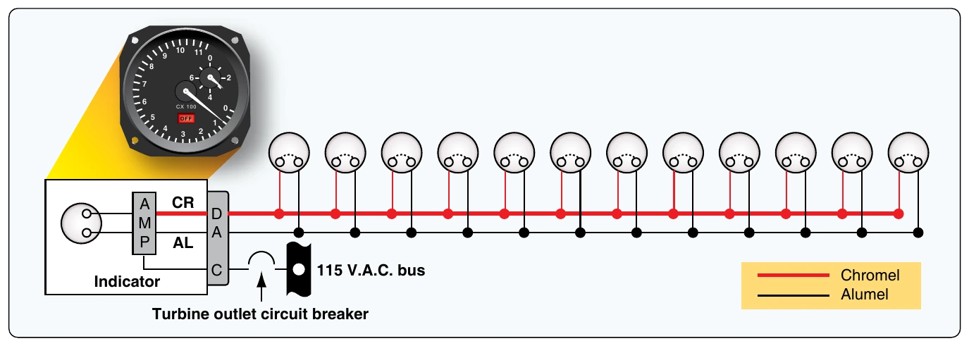
Several thermocouples are used to measure EGT or TIT. They are spaced at intervals around the perimeter of the engine turbine casing or exhaust duct. The tiny thermocouple voltages are typically amplified and used to energize a servomotor that drives the indicator pointer. Gearing a digital drum indication off of the pointer motion is common. [Figure 10-74] The EGT indicator shown is a hermetically sealed unit. The instrument’s scale ranges from 0 °C to 1,200 °C, with a vernier dial in the upper right-hand corner and a power off warning flag located in the lower portion of the dial.
A TIT indicating system provides a visual indication at the instrument panel of the temperature of gases entering the turbine. Numerous thermocouples can be used with the average voltage representing the TIT. Dual thermocouples exist containing two electrically independent junctions within a single probe. One set of these thermocouples is paralleled to transmit signals to the flight deck indicator. The other set of parallel thermocouples provides temperature signals to engine monitoring and control systems. Each circuit is electrically independent, providing dual system reliability.
A schematic for the turbine inlet temperature system for one engine of a four-engine turbine aircraft is shown in
to this system. The indicator contains a bridge circuit, a chopper circuit, a two-phase motor to drive the pointer, and a feedback potentiometer. Also included are a voltage reference circuit, an amplifier, a power-off flag, a power supply, and an over-temperature warning light. Output of the amplifier energizes the variable field of the two-phase motor that positions the indicator main pointer and a digital indicator. The motor also drives the feedback potentiometer to provide a humming signal to stop the drive motor when the correct pointer position, relative to the temperature signal, has been reached. The voltage reference circuit provides a closely regulated reference voltage in the bridge circuit to preclude error from input voltage variation to the indicator power supply.
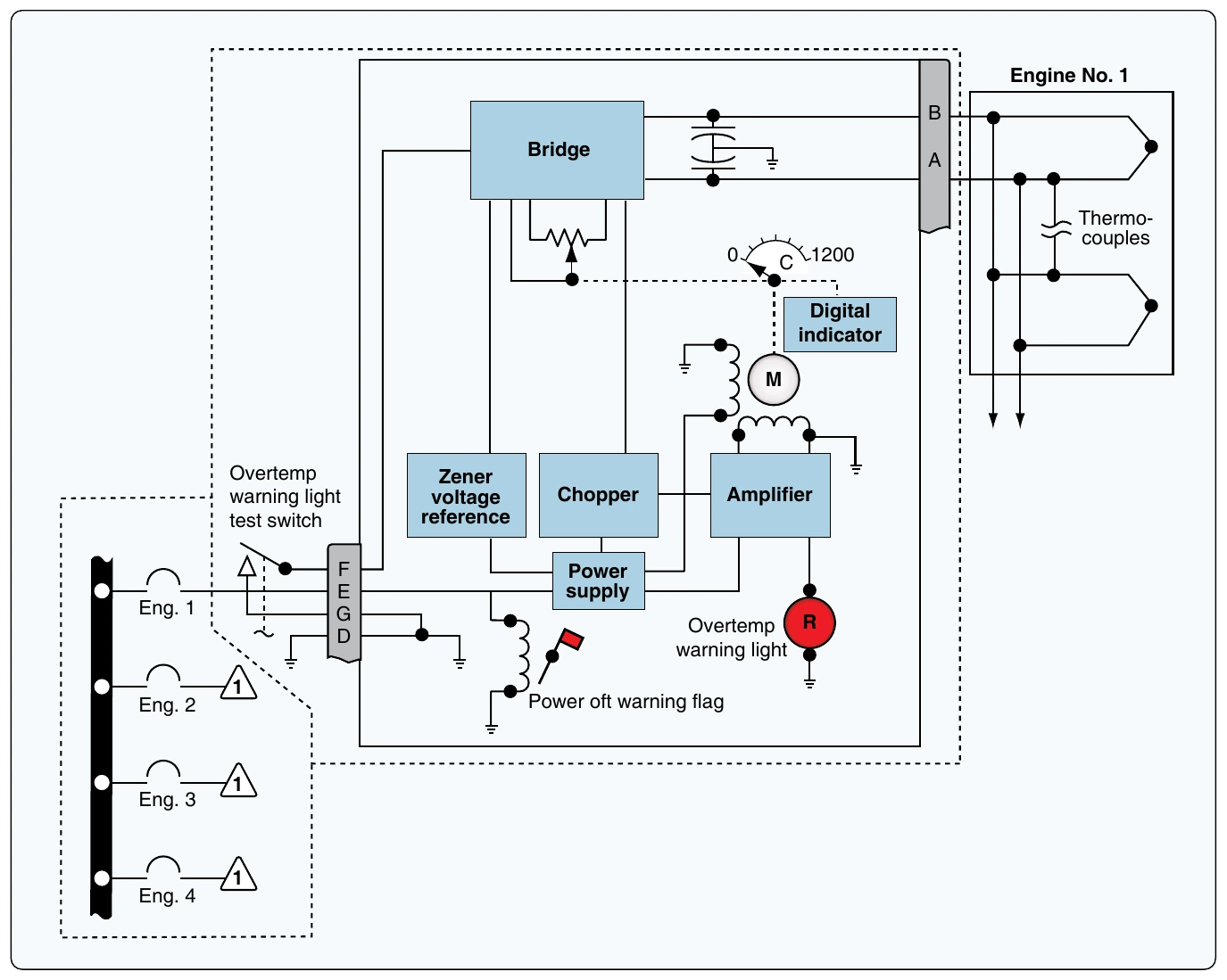
The over-temperature warning light in the indicator illuminates when the TIT reaches a predetermined limit. An external test switch is usually installed so that over-temperature warning lights for all the engines can be tested at the same time. When the test switch is operated, an over-temperature signal is simulated in each indicator temperature control bridge circuit.
Digital flight deck instrumentation systems need not employ resistance-type indicators and adjusted servo-driven thermocouple gauges to provide the pilot with temperature information. Sensor resistance and voltage values are input to the appropriate computer, where they are adjusted, processed, monitored, and output for display on flight deck display panels. They are also sent for use by other computers requiring temperature information for the control and monitoring of various integrated systems.
Total Air Temperature Measurement
Air temperature is a valuable parameter that many performance monitoring and control variables depend on. During flight, static air temperature changes continuously and accurate measurement presents challenges. Below Mach 0.2, a simple resistance-type or bimetallic temperature gauge can provide relatively accurate air temperature information. At faster speeds, friction, the air’s compressibility, and boundary layer behavior make accurate temperature capture more complex. Total air temperature (TAT) is the static air temperature plus any rise in temperature caused by the high-speed movement of the aircraft through the air. The increase in temperature is known as ram rise. TAT-sensing probes are constructed specifically to accurately capture this value and transmit signals for flight deck indication, as well as for use in various engine and aircraft systems.
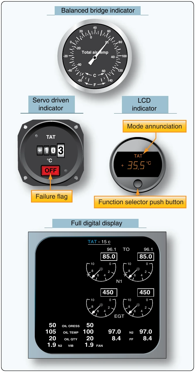
Simple TAT systems include a sensor and an indicator with a built-in resistance balance circuit. Air flow through the sensor is designed so that air with the precise temperature impacts a platinum alloy resistance element. The sensor is engineered to capture temperature variations in terms of varying the resistance of the element. When placed in the bridge circuit, the indicator pointer moves in response to the imbalance caused by the variable resistor.
More complex systems use signal correction technology and amplified signals sent to a servo motor to adjust the indicator in the flight deck. These systems include closely regulated power supply and failure monitoring. They often use numeric drum type readouts but can also be sent to an LCD driver to illuminate LCD displays. Many LCD displays are multifunctional, capable of displaying static air temperature and true airspeed. In fully digital systems, the correction signals are input into the ADC. There, they can be manipulated appropriately for flight deck display or for whichever system requires temperature information. [Figure 10-76]
TAT sensor/probe design is complicated by the potential of ice forming during icing conditions. Left unheated, a probe may cease to function properly. The inclusion of a heating element threatens accurate data collection. Heating the probe must not affect the resistance of the sensor element. [Figure 10-77]