
Chapter 10
Aircraft Systems
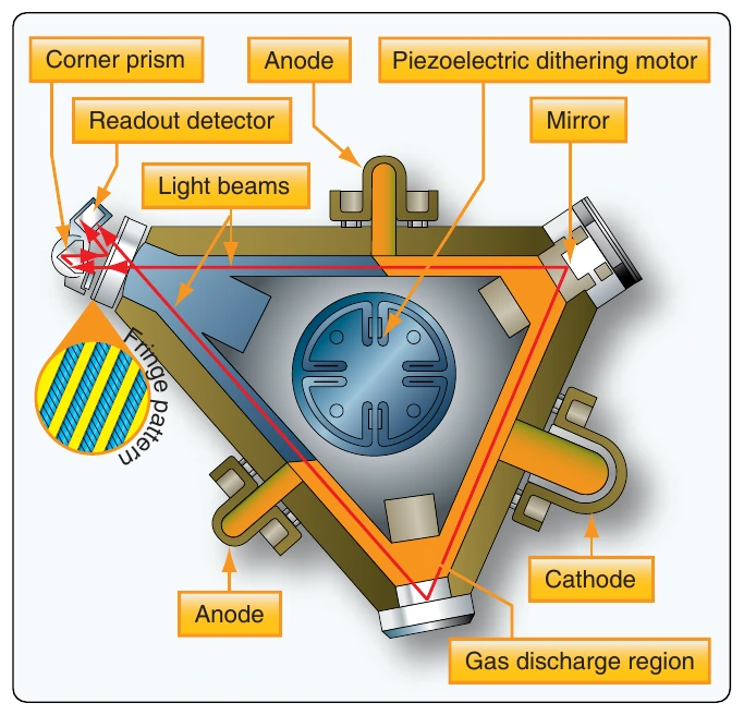
A laser is light amplification by stimulated emission of radiation. A laser operates by exciting atoms in plasma to release electromagnetic energy, or photons. A ring laser gyro produces laser beams that travel in opposite directions around a closed triangular cavity. The wavelength of the light traveling around the loop is fixed. As the loop rotates, the path the lasers must travel lengthens or shortens. The light wavelengths compress or expand to complete travel around the loop as the loop changes its effective length. As the wavelengths change, the frequencies also change. By examining the difference in the frequencies of the two counter-rotating beams of light, the rate at which the path is rotating can be measured. A piezoelectric dithering motor in the center of the unit vibrates to prevent lock-in of the output signal at low rotational speeds. It causes units installed on aircraft to hum when operating. [Figure 10-97]
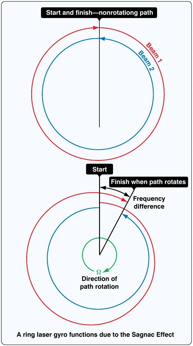
An RLG is remotely mounted so the cavity path rotates around one of the axes of flight. The rate of frequency phase shift detected between the counter-rotating lasers is proportional to the rate that the aircraft is moving about that axis. On aircraft, an RLG is installed for each axis of flight. Output can be used in analog instrumentation and autopilot systems. It is also easily made compatible for use by digital display computers and for digital autopilot computers.
RLGs are very rugged and have a long service life with virtually no maintenance due to their lack of moving parts. They measure movement about an axis extremely quickly and provide continuous output. They are extremely accurate and generally are considered superior to mechanical gyroscopes.
Microelectromechanical-Based Attitude & Directional Systems
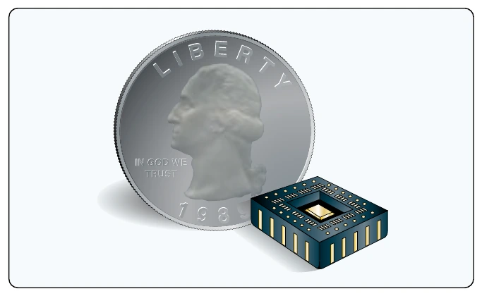
On aircraft, microelectromechanical systems (MEMS) devices save space and weight. Through the use of solid-state MEMS devices, reliability is increased primarily due to the lack of moving parts. The development of MEMS technology for use in aviation instrumentation integrates with the use of ADCs. This newest improvement in technology is low cost and promises to proliferate through all forms of aviation.
MEMS for gyroscopic applications are used in small, general aviation aircraft, as well as larger commercial aircraft. Tiny vibration-based units with resistance and capacitance measuring pick-offs are accurate and reliable and only a few millimeters in length and width. They are normally integrated into a complete micro-electronic solid-state chip designed to yield an output after various conditioning processes are performed. The chips, which are analogous to tiny circuit boards, can be packaged for installation inside a dedicated computer or module that is installed on the aircraft.
While a large mechanical gyroscope spins in a plane, its rigidity in space is used to observe and measure the movement of the aircraft. The basis of operation of many MEMS gyroscopes is the same despite their tiny size. The difference is that a vibrating or oscillating piezoelectric device replaces the spinning, weighted ring of the mechanical gyro. Still, once set in motion, any out-of-plane motion is detectable by varying microvoltages or capacitances detected through geometrically arranged pickups. Since piezoelectric substances have a relationship between movement and electricity, microelectrical stimulation can set a piezoelectric gyro in motion and the tiny voltages produced via the movement in the piezo can be extracted. They can be input as the required variables needed to compute attitude or direction information. [Figure 10-98]
Other Attitude & Directional Systems
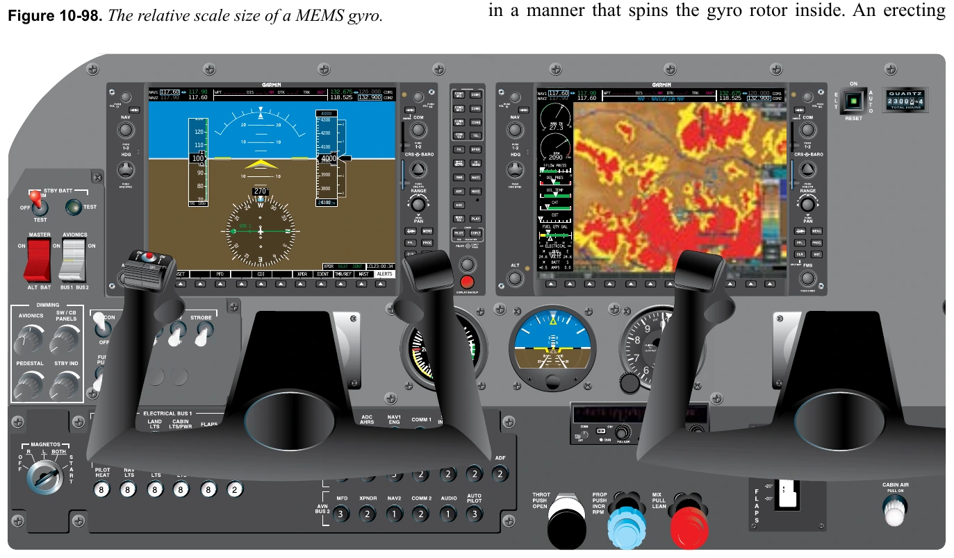
In modern aircraft, attitude heading and reference systems (AHRS) have taken the place of the gyroscope and other individual instruments. While MEMS devices provide part of the attitude information for the system, GPS, solid state magnetometers, solid state accelerometers, and digital air data signals are all combined in an AHRS to compute and output highly reliable information for display on a flight deck panel. [Figure 10-99]
Common Gyroscopic Instruments
Vacuum-Driven Attitude Gyros
The attitude indicator, or artificial horizon, is one of the most essential flight instruments. It gives the pilot pitch and roll information that is especially important when flying without outside visual references. The attitude indicator operates with a gyroscope rotating in the horizontal plane. Thus, it mimics the actual horizon through its rigidity in space. As the aircraft pitches and rolls in relation to the actual horizon, the gyro gimbals allow the aircraft and instrument housing to pitch and roll around the gyro rotor that remains parallel to the ground. A horizontal representation of the airplane in miniature is fixed to the instrument housing. A painted semisphere simulating the horizon, the sky, and the ground is attached to the gyro gimbals. The sky and ground meet at what is called the horizon bar. The relationship between the horizon bar and the miniature airplane are the same as those of the aircraft and the actual horizon. Graduated scales reference the degrees of pitch and roll. Often, an adjustment knob allows pilots of varying heights to place the horizon bar at an appropriate level. [Figure 10-100]
In a typical vacuum-driven attitude gyro system, air is pulled through a filter and then through the attitude indicator mechanism is built into the instrument to assist in keeping the gyro rotor rotating in the intended plane. Precession caused by bearing friction makes this necessary. After air engages the scalloped drive on the rotor, it flows from the instrument to the vacuum pump through four ports. These ports all exhaust the same amount of air when the gyro is rotating in plane. When the gyro rotates out of plane, air tends to port out of one side more than another. Vanes close to prevent this, causing more air to flow out of the opposite side. The force from this unequal venting of the air re-erects the gyro rotor. [Figure 10-101]
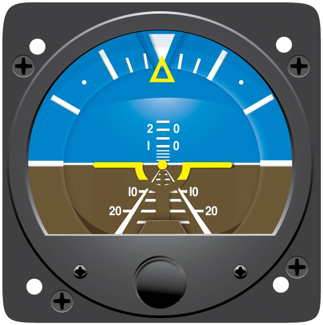
Early vacuum-driven attitude indicators were limited in how far the aircraft could pitch or roll before the gyro gimbals contacted stops, causing abrupt precession and tumbling of the gyro. Many of these gyros include a caging device. It is used to erect the rotor to its normal operating position prior to flight or after tumbling. A flag indicates that the gyro must be uncaged before use. More modern gyroscopic instruments are built so they do not tumble, regardless of the angular movement of the aircraft about its axes.
In addition to the contamination potential introduced by the air-drive system, other shortcomings exist in the performance of vacuum-driven attitude indicators. Some are induced by the erection mechanism. The pendulous vanes that move to direct airflow out of the gyro respond not only to forces caused by a deviation from the intended plane of rotation, but centrifugal force experienced during turns also causes the vanes to allow asymmetric porting of the gyro vacuum air. The result is inaccurate display of the aircraft’s attitude, especially 2 0 I 0