
Chapter 10
Aircraft Systems
I0 I0 20 20
the aircraft in level flight (left) and in a climbing right turn (right).
in skids and steep banked turns. Also, abrupt acceleration and deceleration imposes forces on the gyro rotor. Suspended in its gimbals, it acts similar to an accelerometer, resulting in a false nose-up or nose-down indication. Pilots must learn to recognize these errors and adjust accordingly.
Electric Attitude Indicators
Electric attitude indicators are very similar to vacuum-driven gyro indicators. The main difference is in the drive mechanism. Inside the gimbals of an electric gyro, a small squirrel cage electric motor is the rotor. It is typically driven by 115-volt, 400-cycle AC. It turns at approximately 21,000 rpm.
Other characteristics of the vacuum-driven gyro are shared by the electric gyro. The rotor is still oriented in the horizontal plane. The free gyro gimbals allow the aircraft and instrument case to rotate around the gyro rotor that remains rigid in space. A miniature airplane fixed to the instrument case indicates the aircraft’s attitude against the moving horizon bar behind it.
Electric attitude indicators address some of the shortcomings of vacuum-driven attitude indicators. Since there is no air flowing through an electric attitude indicator, air filters, regulators, plumbing lines and vacuum pump(s) are not needed. Contamination from dirt in the air is not an issue, resulting in the potential for longer bearing life and less precession. Erection mechanism ports are not employed, so pendulous vanes responsive to centrifugal forces are eliminated.
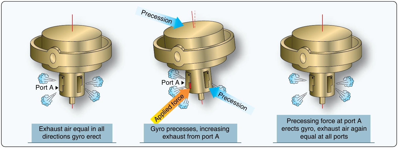
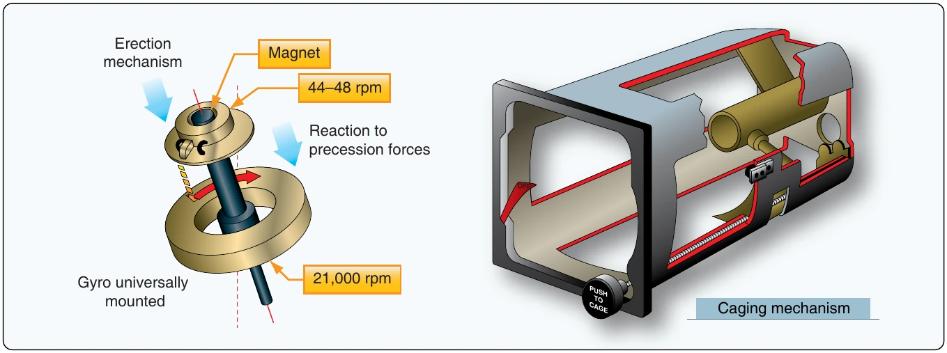
It is still possible that the gyro may experience precession and need to be erected. This is done with magnets rather than vent ports. A magnet attached to the top of the gyro shaft spins at approximately 21,000 rpm. Around this magnet, but not attached to it, is a sleeve that is rotated by magnetic attraction at approximately 44 to 48 rpm. Steel balls are free to move around the sleeve. If the pull of gravity is not aligned with the axis of the gyro, the balls fall to the low side. The resulting precession re-aligns the axis of rotation vertically.
Typically, electric attitude indicator gyros can be caged manually by a lever and cam mechanism to provide rapid erection. When the instrument is not getting sufficient power for normal operation, an off flag appears in the upper right hand face of the instrument. [Figure 10-102]
Gyroscopic Direction Indicator or Directional Gyro (DG)
The gyroscopic direction indicator or directional gyro (DG) is often the primary instrument for direction. Because a magnetic compass fluctuates so much, a gyro aligned with the magnetic compass gives a much more stable heading indication. Gyroscopic direction indicators are located at the center base of the instrument panel basic T.
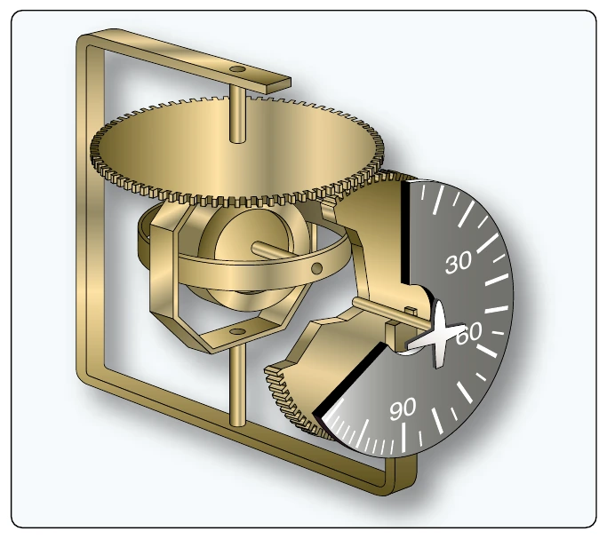
A vacuum-powered DG is common on many light aircraft. Its basis for operation is the gyro’s rigidity in space. The gyro rotor spins in the vertical plane and stays aligned with the direction to which it is set. The aircraft and instrument case moves around the rigid gyro. This causes a vertical compass card that is geared to the rotor gimbal to move. It is calibrated in degrees, usually with every 30 degrees labeled. The nose of a small, fixed airplane on the instrument glass indicates the aircraft’s heading. [Figure 10-103]
Vacuum-driven direction indicators have many of the same basic gyroscopic instrument issues as attitude indicators. Built-in compensation for precession varies and a caging device is usually found. Periodic manual realignment with the magnetic compass by the pilot is required during flight.
Turn Coordinators
Many aircraft make use of a turn coordinator. The rotor of the gyro in a turn coordinator is canted upwards 30°. As such, it responds not only to movement about the vertical axis, but also to roll movements about the longitudinal axis. This is useful because it is necessary to roll an aircraft to turn it about the vertical axis. Instrument indication of roll, therefore, is the earliest possible warning of a departure from straight-and-level flight.
Typically, the face of the turn coordinator has a small airplane symbol. The wing tips of the airplane provide the indication of level flight and the rate at which the aircraft is turning. [Figure 10-104]