Chapter 10
Aircraft Systems
The turn-and-slip indicator may also be referred to as the turn-and-bank indicator, or needle-and-ball indicator. Regardless, it shows the correct execution of a turn while banking the aircraft and indicates movement about the vertical axis of the aircraft (yaw). Most turn-and-slip indicators are located below the airspeed indicator of the instrument panel basic T, just to the left of the direction indicator.
The turn-and-slip indicator is actually two separate devices built into the same instrument housing: a turn indicator pointer and slip indicator ball. The turn pointer is operated by a gyro that can be driven by a vacuum, air pressure, or by electricity. The ball is a completely independent device. It is a round agate, or steel ball, in a glass tube filled with dampening fluid. It moves in response to gravity and centrifugal force experienced in a turn. The gyro turn-and-slip indicator may be driven electrically or pneumatically (by vacuum or air pressure).
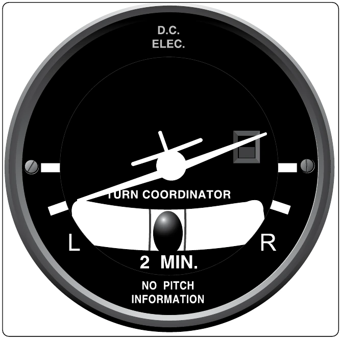
Turn indicators vary. They all indicate the rate at which the aircraft is turning. Three degrees of turn per second cause an aircraft to turn 360° in 2 minutes. This is considered a standard turn. This rate can be indicated with marks right and left of the pointer, which normally rests in the vertical position. Sometimes, no marks are present, and the width of the pointer is used as the calibration device. In this case, one pointer width deflection from vertical is equal to the 3° per second standard 2-minute turn rate. Faster aircraft tend to turn more slowly and have graduations or labels that indicate 4-minute turns. In other words, a pointer’s width or alignment with a graduation mark on this instrument indicates that the aircraft is turning a 11⁄2° per second and completes a 360° turn in 4 minutes. It is customary to placard the instrument face with words indicating whether it is a 2-or 4-minute turn indicator. [Figure 10-105]
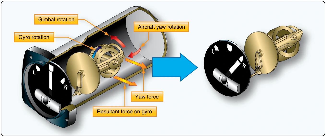
The turn pointer indicates the rate at which an aircraft is turning about its vertical axis. It does so by using the precession of a gyro to tilt a pointer. The gyro spins in a vertical plane aligned with the longitudinal axis of the aircraft. When the aircraft rotates about its vertical axis during a turn, the force experienced by the spinning gyro is exerted about the vertical axis. Due to precession, the reaction of the gyro rotor is 90° further around the gyro in the direction of spin. This means the reaction to the force around the vertical axis is movement around the longitudinal axis of the aircraft. This causes the top of the rotor to tilt to the left or right. The pointer is attached with linkage that makes the pointer deflect in the opposite direction, which matches the direction of turn. So, the aircraft’s turn around the vertical axis is indicated around the longitudinal axis on the gauge. This is intuitive to the pilot when regarding the instrument, since the pointer indicates in the same direction as the turn. [Figure 10-106]
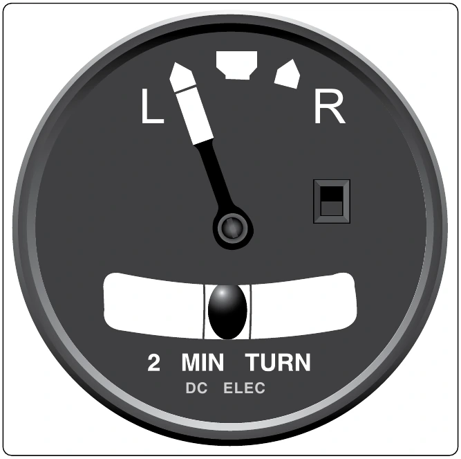
The slip indicator (ball) part of the instrument is an inclinometer. The ball responds only to gravity during coordinated straight-and-level flight. Thus, it rests in the lowest part of the curved glass between the reference wires. When a turn is initiated, and the aircraft is banked, both gravity and the centrifugal force of the turn act upon the ball. If the turn is coordinated, the ball remains in place. Should a skidding turn exist, the centrifugal force exceeds the force of gravity on the ball and it moves in the direction of the outside of the turn. During a slipping turn, there is more bank than needed, and gravity is greater than the centrifugal force acting on the ball. The ball moves in the curved glass toward the inside of the turn.
As mentioned previously, often power for the turn-and-slip indicator gyro is electrical if the attitude and direction indicators are vacuum powered. This allows limited operation off battery power should the vacuum system and the electric generator fail. The directional and attitude information from the turn-and-slip indicator, combined with information from the pitot static instruments, allow continued safe emergency operation of the aircraft.
Electrically powered turn-and-slip indicators are usually DC powered. Vacuum-powered turn-and-slip indicators are usually run on less vacuum (approximately 2 "Hg) than fully gimbaled attitude and direction indicators. Regardless, proper vacuum must be maintained for accurate turn rate information to be displayed.
Autopilot Systems
An aircraft automatic pilot system controls the aircraft without the pilot directly maneuvering the controls. The autopilot maintains the aircraft’s attitude and/or direction and returns the aircraft to that condition when it is displaced from it. Automatic pilot systems are capable of keeping aircraft stabilized laterally, vertically, and longitudinally.
The primary purpose of an autopilot system is to reduce the work strain and fatigue of controlling the aircraft during long flights. Most autopilots have both manual and automatic modes of operation. In the manual mode, the pilot selects each maneuver and makes small inputs into an autopilot controller. The autopilot system moves the control surfaces of the aircraft to perform the maneuver. In automatic mode, the pilot selects the attitude and direction desired for a flight segment. The autopilot then moves the control surfaces to attain and maintain these parameters.
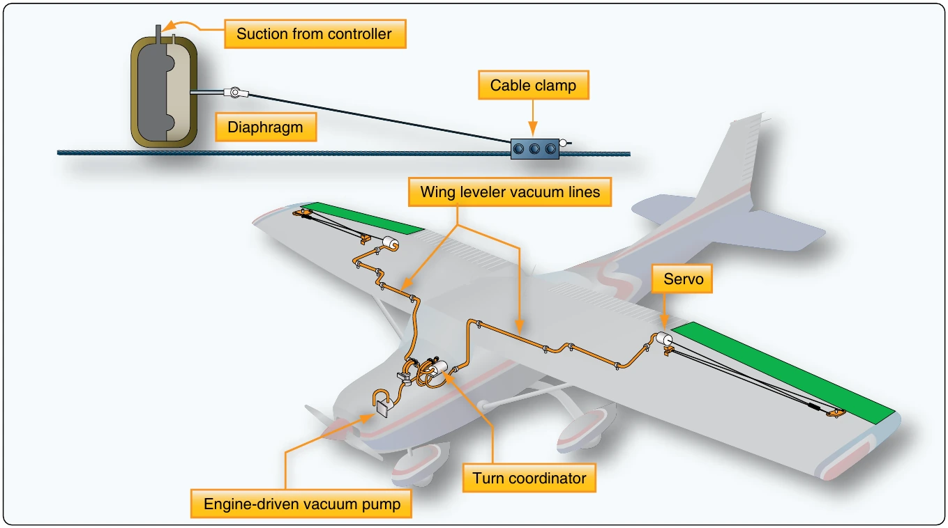
Autopilot systems provide for one-, two-, or three-axis control of an aircraft. Those that manage the aircraft around only one axis control the ailerons. They are single-axis autopilots, known as wing leveler systems, usually found on light aircraft. [Figure 10-107] Other autopilots are two-axis systems that control the ailerons and elevators. Three-axis autopilots control the ailerons, elevators, and the rudder. Two-and three-axis autopilot systems can be found on aircraft of all sizes.
There are many autopilot systems available. They feature a wide range of capabilities and complexity. Light aircraft typically have autopilots with fewer capabilities than high-performance and transport category aircraft. Integration of navigation functions is common, even on light aircraft autopilots. As autopilots increase in complexity, they not only manipulate the flight control surfaces, but other flight parameters as well.
Some modern small aircraft, high-performance, and transport category aircraft have very elaborate autopilot systems known as automatic flight control systems (AFCS). These three-axis systems go far beyond steering the airplane. They control the aircraft during climbs, descents, cruise, and approach to landing. Some even integrate an auto-throttle function that automatically controls engine thrust that makes auto-landings possible.
For further automatic control, flight management systems (FMS) have been developed. Through the use of computers, an entire flight profile can be programmed ahead of time allowing the pilot to supervise its execution. An FMS computer coordinates nearly every aspect of a flight, including the autopilot and auto throttle systems, navigation route selection, fuel management schemes, and more.
Basis for Autopilot Operation
The basis for autopilot system operation is error correction. When an aircraft fails to meet the conditions selected, an error is said to have occurred. The autopilot system automatically corrects that error and restores the aircraft to the flight attitude desired by the pilot. There are two basic ways modern autopilot systems do this. One is position based and the other is rate based. A position based autopilot manipulates the aircraft’s controls so that any deviation from the desired attitude of the aircraft is corrected. This is done by memorizing the desired aircraft attitude and moving the control surfaces so that the aircraft returns to that attitude. Rate based autopilots use information about the rate of movement of the aircraft and move control surfaces to counter the rate of change that causes the error. Most large aircraft use rate-based autopilot systems. Small aircraft may use either.