
Chapter 10
Aircraft Systems
Autopilot Functions
The following autopilot system description is presented to show the function of a simple analog autopilot. Most autopilots are far more sophisticated; however, many of the operating fundamentals are similar.
The automatic pilot system flies the aircraft by using electrical signals developed in gyro-sensing units. These units are connected to flight instruments that indicate direction, rate of turn, bank, or pitch. If the flight attitude or magnetic heading is changed, electrical signals are developed in the gyros. These signals are sent to the autopilot computer/amplifier and are used to control the operation of servo units.
A servo for each of the three control channels converts electrical signals into mechanical force, which moves the control surface in response to corrective signals or pilot commands. The rudder channel receives two signals that determine when and how much the rudder moves. The first signal is a course signal derived from a compass system. As long as the aircraft remains on the magnetic heading it was on when the autopilot was engaged, no signal develops. But, any deviation causes the compass system to send a signal to the rudder channel that is proportional to the angular displacement of the aircraft from the preset heading.
The second signal received by the rudder channel is the rate signal that provides information anytime the aircraft is turning about the vertical axis. This information is provided by the turn-and-bank indicator gyro. When the aircraft attempts to turn off course, the rate gyro develops a signal proportional to the rate of turn, and the course gyro develops a signal proportional to the amount of displacement. The two signals are sent to the rudder channel of the amplifier, where they are combined, and their strength is increased. The amplified signal is then sent to the rudder servo. The servo turns the rudder in the proper direction to return the aircraft to the selected magnetic heading.
As the rudder surface moves, a follow-up signal is developed that opposes the input signal. When the two signals are equal in magnitude, the servo stops moving. As the aircraft arrives on course, the course signal reaches a zero value, and the rudder is returned to the streamline position by the follow-up signal.
The aileron channel receives its input signal from a transmitter located in the gyro horizon indicator. Any movement of the aircraft about its longitudinal axis causes the gyro-sensing unit to develop a signal to correct for the movement. This signal is amplified, phase detected, and sent to the aileron servo, which moves the aileron control surfaces to correct for the error. As the aileron surfaces move, a follow-up signal builds up in opposition to the input signal. When the two signals are equal in magnitude, the servo stops moving. Since the ailerons are displaced from the streamline, the aircraft now starts moving back toward level flight with the input signal becoming smaller and the follow-up signal driving the control surfaces back toward the streamline position. When the aircraft has returned to level flight roll attitude, the input signal is again zero. At the same time, the control surfaces are streamlined, and the follow-up signal is zero.
The elevator channel circuits are similar to those of the aileron channel, with the exception that the elevator channel detects and corrects changes in pitch attitude of the aircraft.
altitude pressure diaphragm is used. Similar to the attitude and directional gyros, the altitude unit generates error signals when the aircraft has moved from a preselected altitude. This is known as an altitude hold function. The signals control the pitch servos, which move to correct the error. An altitude select function causes the signals to continuously be sent to the pitch servos until a preselected altitude has been reached. The aircraft then maintains the preselected altitude using altitude hold signals.
Yaw Dampening
Many aircraft have a tendency to oscillate around their vertical axis while flying a fixed heading. Near continuous rudder input is needed to counteract this effect. A yaw damper is used to correct this motion. It can be part of an autopilot system or a completely independent unit. A yaw damper receives error signals from the turn coordinator rate gyro. Oscillating yaw motion is counteracted by rudder movement, which is made automatically by the rudder servo(s) in response to the polarity and magnitude of the error signal.
Automatic Flight Control System (AFCS)
An aircraft autopilot with many features and various autopilot related systems integrated into a single system is called an automatic flight control system (AFCS). These were formerly found only on high-performance aircraft. Currently, due to advances in digital technology for aircraft, modern aircraft of any size may have AFCS.
AFCS capabilities vary from system to system. Some of the advances beyond ordinary autopilot systems are the extent of programmability, the level of integration of navigational aids, the integration of flight director and autothrottle systems, and combining of the command elements of these various systems into a single integrated flight control human interface. [Figure 10-112]
It is at the AFCS level of integration that an autothrottle system is integrated into the flight director and autopilot systems with glide scope modes so that auto landings are possible. Small general aviation aircraft being produced with AFCS may lack the throttle-dependent features.
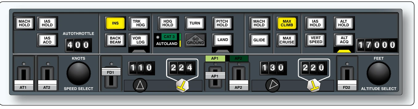
Modern general aviation AFCS are fully integrated with digital attitude heading and reference systems (AHRS) and navigational aids including glideslope. They also contain modern computer architecture for the autopilot (and flight director systems) that is slightly different than described above for analog autopilot systems. Functionality is distributed across a number of interrelated computers and includes the use of intelligent servos that handle some of the error correction calculations. The servos communicate with dedicated avionics computers and display unit computers through a control panel, while no central autopilot computer exists. [Figure 10-113]
Flight Director Systems
A flight director system is an instrument system consisting of electronic components that compute and indicate the aircraft attitude required to attain and maintain a preselected flight condition. A command bar on the aircraft’s attitude indicator shows the pilot how much and in what direction the attitude of the aircraft must be changed to achieve the desired result. The computed command indications relieve the pilot of many of the mental calculations required for instrument flights, such as interception angles, wind drift correction, and rates of climb and descent.
Essentially, a flight director system is an autopilot system without the servos. All of the same sensing and computations are made, but the pilot controls the airplane and makes maneuvers by following the commands displayed on the instrument panel. Flight director systems can be part of an autopilot system or exist on aircraft that do not possess full autopilot systems. Many autopilot systems allow for the option of engaging or disengaging a flight director display.