Chapter 10
Aircraft Systems
Computerized electronic flight instrument systems have additional benefits. The solid-state nature of the components increases reliability. Also, microprocessors, data buses, and LCDs all save space and weight. The following systems have been developed and utilized on aircraft for a number of years. New systems and computer architecture are sure to come in the future.
Electronic Flight Instrument System (EFIS)
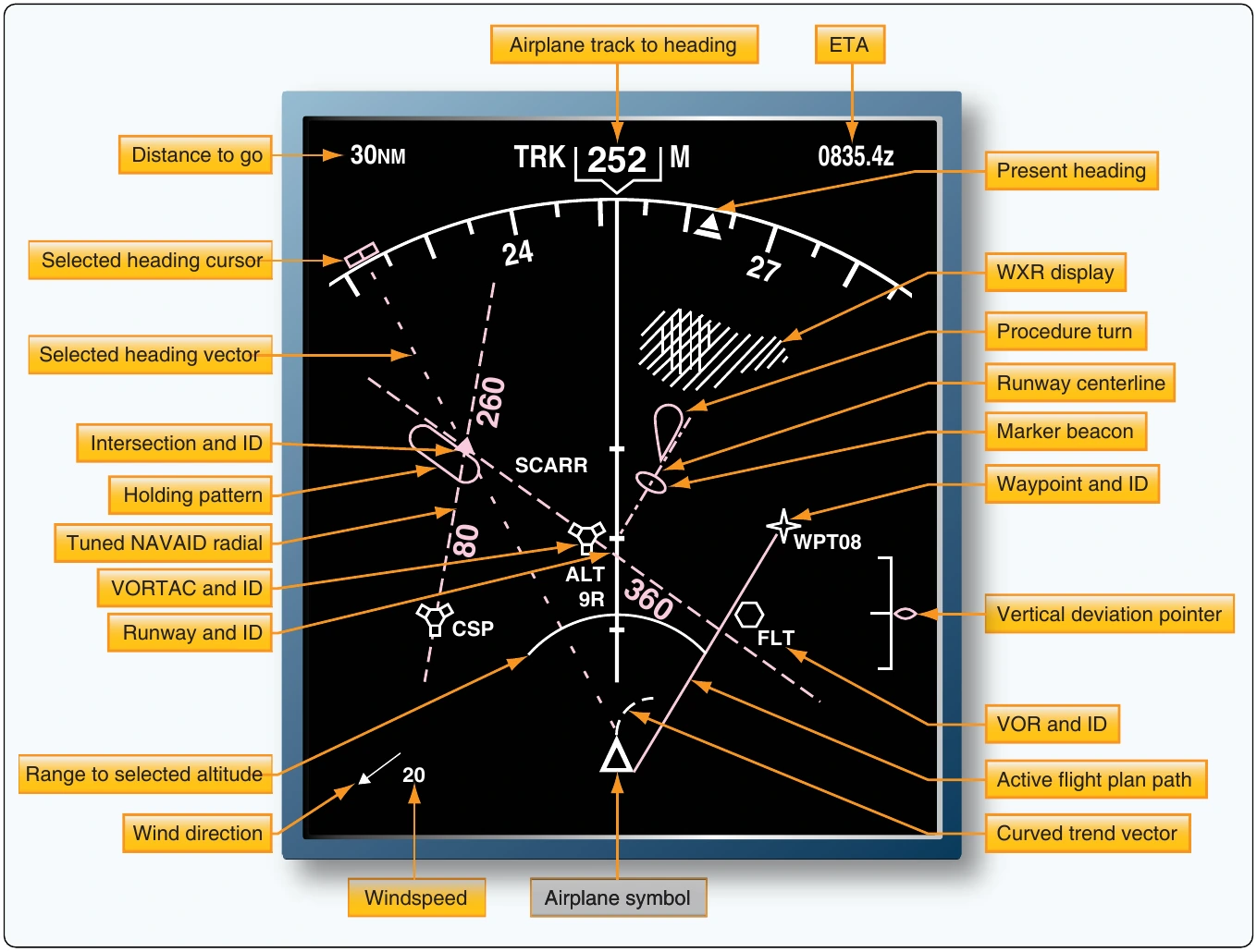
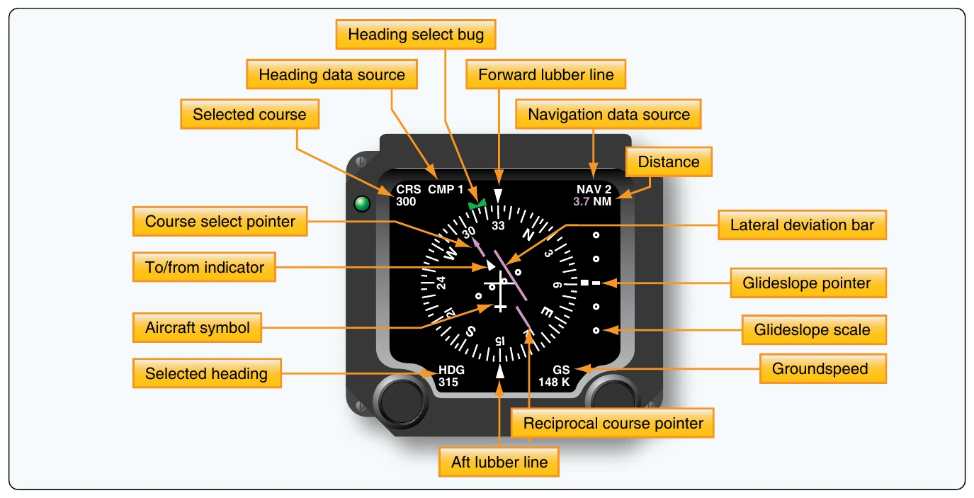
The flight instruments were the first to adopt computer technology and utilize flat screen, multifunctional displays (MFD). EFIS uses dedicated signal generators to drive two independent displays in the center of the basic T. The attitude indicator and directional gyro are replaced by cathode ray tubes (CRT) used to display EADI and EHSI presentations. These enhanced instruments operate alongside ordinary mechanic and electric instruments with limited integration. Still, EADI and EHSI technology is very desirable, reducing workload and panel scan with the added safety provided by integration of navigation information as described.
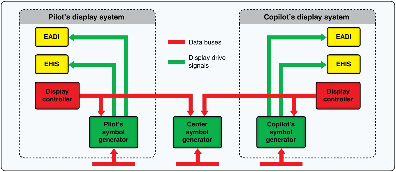
Early EFIS systems have analog technology, while newer models may be digital systems. The signal generators receive information from attitude and navigation equipment. Through a display controller, the pilot can select the various mode or screen features wishing to be displayed. Independent dedicated pilot and copilot systems are normal. A third, backup symbol generator is available to assume operation should one of the two primary units fail. [Figure 10-118]
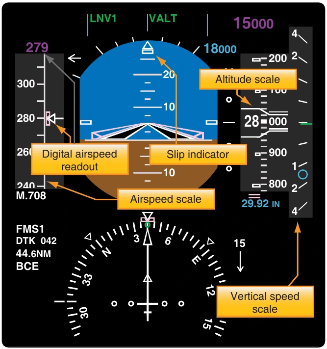
Electronic depiction of ADI and HSI information is the core purpose of an EFIS system. Its expanded size and capabilities over traditional gauges allow for integration of even more flight instrument data. A vertical airspeed scale is typically displayed just left of the attitude field. This is in the same relative position as the airspeed indicator in an analog basic T instrument panel. To the right of the attitude field, many EFIS systems display an altitude and vertical speed scale. Since most EFIS EADI depictions include the inclinometer, normally part of the turn coordinator, all of the basic flight instruments are depicted by the EFIS display. [Figure 10-119]
Electronic Centralized Aircraft Monitor (ECAM)
The pilot’s workload on all aircraft includes continuous monitoring of the flight instruments and the sky outside of the aircraft. It also includes vigilant scrutiny for proper operation of the engine and airframe systems. On transport category aircraft, this can mean monitoring numerous gauges in addition to maneuvering the aircraft. The electronic centralized aircraft monitoring (ECAM) system is designed to assist with this duty.
The basic concept behind ECAM (and other monitoring systems) is automatic performance of monitoring duties for the pilot. When a problem is detected, or a failure occurs, the primary display, along with an aural and visual cue, alerts the pilot. Corrective action that needs to be taken is displayed, as well as suggested action due to the failure. By performing system monitoring automatically, the pilot is free to fly the aircraft until a problem occurs.
Early ECAM systems only monitor airframe systems. Engine parameters are displayed on traditional full-time flight deck gauges. Later model ECAM systems incorporate engine displays, as well as airframe.
An ECAM system has two CRT monitors. In newer aircraft, these may be LCD. The left or upper monitor, depending on the aircraft panel layout, displays information on system status and any warnings associated corrective actions. This is done in a checklist format. The right or lower monitor displays accompanying system information in a pictorial form, such as a diagram of the system being referred to on the primary monitor.
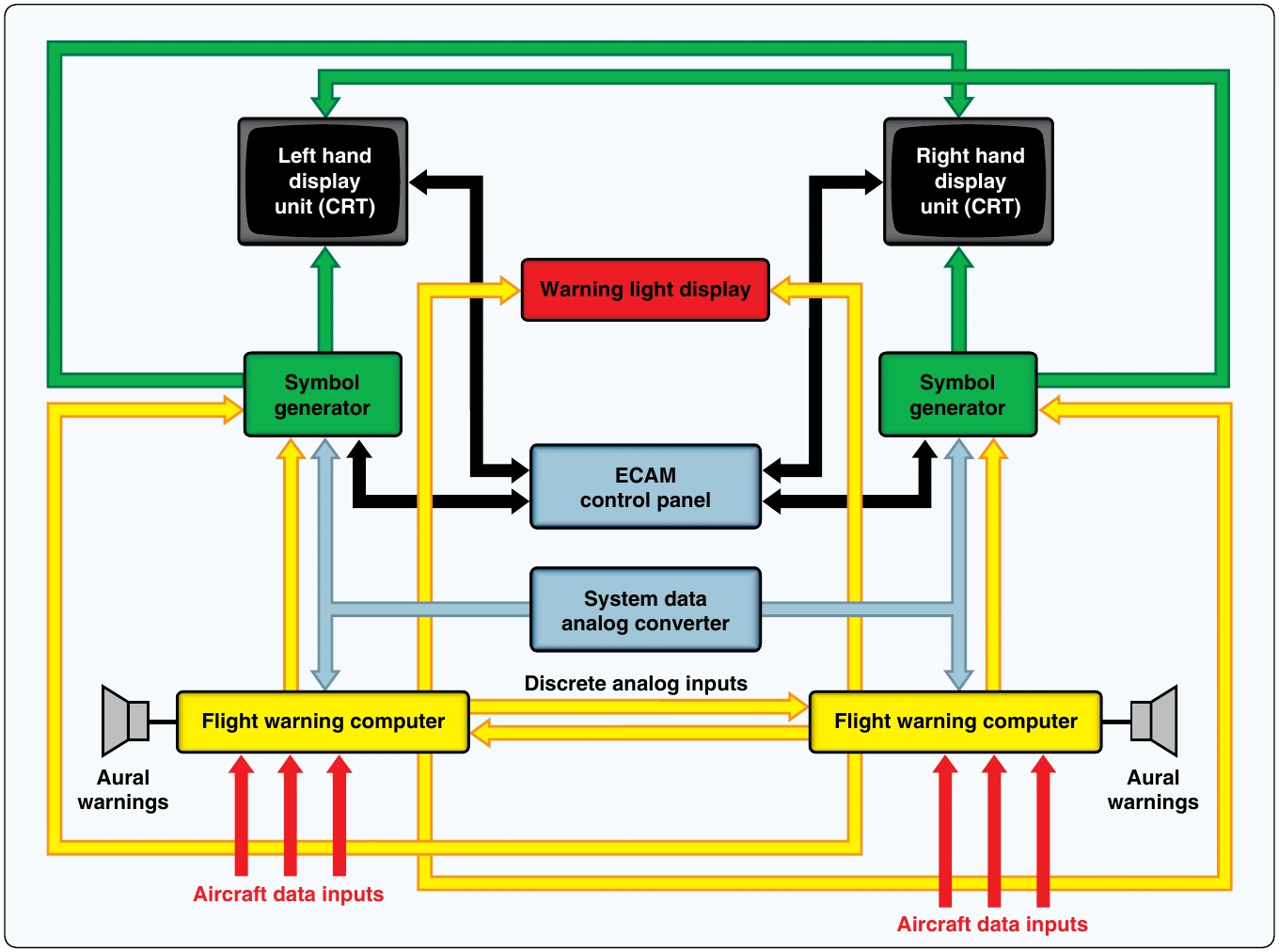
The ECAM monitors are typically powered by separate signal generators. Aircraft data inputs are fed into two flight warning computers. Analog inputs are first fed through a system data analog converter and then into the warning computers. The warning computers process the information and forward information to the signal generators to illuminate the monitors. [Figure 10-120]
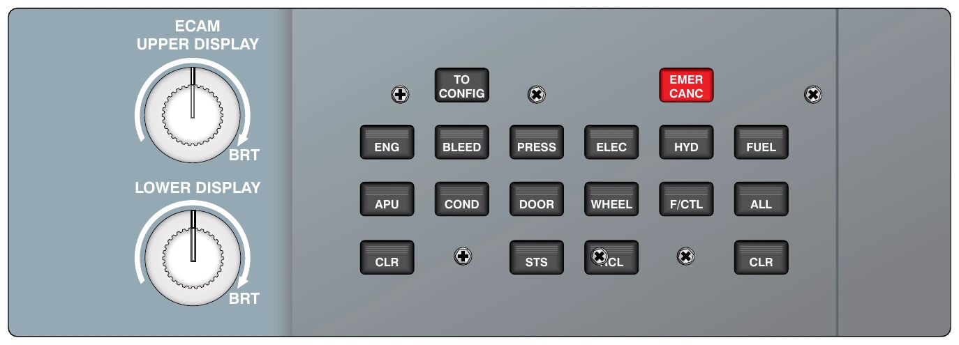
There are four basic modes to the ECAM system: flight phase, advisory, failure related, and manual. The flight phase mode is normally used. The phases are: preflight, takeoff, climb, cruise, descent, approach, and post landing. Advisory and failure–related modes will appear automatically as the situation requires. When an advisory is shown on the primary monitor, the secondary monitor will automatically display the system schematic with numerical values. The same is true for the failure-related mode, which takes precedent over all other modes regardless of which mode is selected at the time of the failure. Color coding is used on the displays to draw attention to matters in order of importance. Display modes are selected via a separate ECAM control panel shown in
The manual mode of an ECAM is set by pressing one of the synoptic display buttons on the control panel. This allows the display of system diagrams. A failure warning or advisory event will cancel this view. [Figure 10-122]
ECAM flight warning computers self-test upon startup. The signal generators are also tested.A maintenance panel allows for testing annunciation and further testing upon demand. BITE stands for built-in test equipment. It is standard for monitoring systems to monitor themselves as well as the aircraft systems. All of the system inputs to the flight warning computers can also be tested for continuity from this panel, as well as inputs and outputs of the system data analog converter. Any individual system faults will be listed on the primary display as normal. Faults in the flight warning computers and signal generators will annunciate on the maintenance panel. [Figure 10-123] Follow the manufacturer’s guidelines when testing ECAM and related systems.