
Chapter 10
Aircraft Systems
Nearly all of the pressure information needed for engine, airframe, and flight instruments can be captured and/or calculated through the use of solid-state pressure sensors in combination with temperature sensors. But continued use of aneroid devices for comparisons involving absolute pressure is notable. Solid-state pressure-sensing systems are remote sensing systems. The sensors are mounted on the aircraft at convenient and effective locations.
Types of Pressure
Pressure is a comparison between two forces. Absolute pressure exists when a force is compared to a total vacuum, or absolutely no pressure. It is necessary to define absolute pressure, because the air in the atmosphere is always exerting pressure on everything. Even when it seems there is no pressure being applied, like when a balloon is deflated, there is still atmospheric pressure inside and outside of the balloon. To measure that atmospheric pressure, it is necessary to compare it to a total absence of pressure, such as in a vacuum. Many aircraft instruments make use of absolute pressure values, such as the altimeter, the rate-of-climb indicator, and the manifold pressure gauge. As stated, this is usually done with an aneroid.
The most common type of pressure measurement is gauge pressure. This is the difference between the pressure to be measured and the atmospheric pressure. The gauge pressure inside the deflated balloon is therefore 0 pounds per square inch (psi) because the pressure inside the balloon is equal to the pressure outside the balloon. Gauge pressure is easily measured and is obtained by ignoring the fact that the atmosphere is always exerting its pressure on everything. For example, a tire is filled with air to 32 psi at a sea level location and checked with a gauge to read 32 psi, which is the gauge pressure. The approximately 14.7 psi of air pressing on the outside of the tire is ignored. The absolute pressure in the tire is 32 psi plus the 14.7 psi that is needed to balance the 14.7 psi on the outside of the tire. So, the tire’s absolute pressure is approximately 46.7 psi. If the same tire is inflated to 32 psi at a location 10,000 feet above sea level, the air pressure on the outside of the tire would only be approximately 10 psi, due to the thinner atmosphere. The pressure inside the tire required to balance this would be 32 psi plus 10 psi, making the absolute pressure of the tire 42 psi. So, the same tire with the same amount of inflation and performance characteristics has different absolute pressure values. Gauge pressure, however, remains the same, indicating the tires are inflated identically. It this case, gauge pressure is more useful in informing us of the condition of the tire.
Gauge pressure measurements are simple and widely useful. They eliminate the need to measure varying atmospheric pressure to indicate or monitor a particular pressure situation. Gauge pressure should be assumed, unless otherwise indicated, or unless the pressure measurement is of a type known to require absolute pressure.
In many instances in aviation, it is desirable to compare the pressures of two different elements to arrive at useful information for operating the aircraft. When two pressures are compared in a gauge, the measurement is known as differential pressure and the gauge is a differential pressure gauge. An aircraft’s airspeed indicator is a differential pressure gauge. It compares ambient air pressure with ram air pressure to determine how fast the aircraft is moving through the air. A turbine’s engine pressure ratio (EPR) gauge is also a differential pressure gauge. It compares the pressure at the inlet of the engine with that at the outlet to indicate the thrust developed by the engine. Both of these differential pressure gauges and others are discussed further in this chapter and throughout this handbook.
In aviation, there is also a commonly used pressure known as standard pressure. Standard pressure refers to an established or standard value that has been created for atmospheric pressure. This standard pressure value is 29.92 inches of mercury ("Hg), 1,013.2 hectopascal (hPa), or 14.7 psi. It is part of a standard day that has been established that includes a standard temperature of 15 °C at sea level. Specific standard day values have also been established for air density, volume, and viscosity. All of these values are developed averages since the atmosphere is continuously fluctuating. They are used by engineers when designing instrument systems and are sometimes used by technicians and pilots. Often, using a standard value for atmospheric pressure is more desirable than using the actual value. For example, at 18,000 feet and above, all aircraft use 29.92 "Hg as a reference pressure for their instruments to indicate altitude. This results in altitude indications in all flight decks being identical. Therefore, an accurate means is established for maintaining vertical separation of aircraft flying at these high altitudes.
Pressure Instruments
Engine Oil Pressure
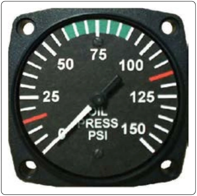
The most important instrument used by the pilot to perceive the health of an engine is the engine oil pressure gauge. [Figure 10-13] Oil pressure is usually indicated in pounds per square inch (psi). The normal operating range is typically represented by a green arc on the circular gauge. For exact acceptable operating range, consult the manufacturer’s operating and maintenance data.
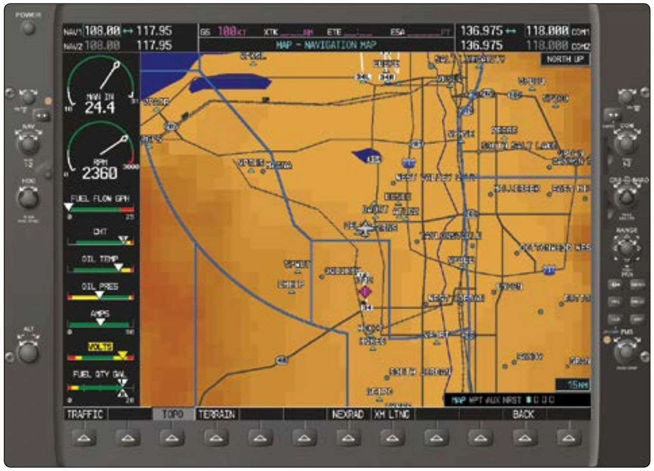
In reciprocating and turbine engines, oil is used to lubricate and cool bearing surfaces where parts are rotating or sliding past each other at high speeds. A loss of pressurized oil to these areas would rapidly cause excessive friction and over-temperature conditions, leading to catastrophic engine failure. As mentioned, aircraft using analog instruments often use direct reading Bourdon tube oil pressure gauges. Figure 10-13 shows the instrument face of a typical oil pressure gauge of this type. Digital instrument systems use an analog or digital remote oil pressure sensing unit that sends output to the computer, driving the display of oil pressure value(s) on the aircraft’s flight deck display screens. Oil pressure may be displayed in a circular or linear gauge fashion and may even include a numerical value on screen. Often, oil pressure is grouped with other engine parameter displays on the same page or portion of a page on the display. Figure 10-14 shows this grouping on a Garmin G1000 digital instrument display system for general aviation aircraft.
Manifold Pressure
In reciprocating engine aircraft, the manifold pressure gauge indicates the pressure of the air in the engine’s induction manifold. This is an indication of power being developed by the engine. The higher the pressure of the fuel air mixture going into the engine, the more power it can produce. For normally aspirated engines, maximum manifold pressure would be slightly less than the ambient atmospheric pressure.
Turbocharged or supercharged engines pressurize the air being mixed with the fuel, so full power indications are above the ambient atmospheric pressure.
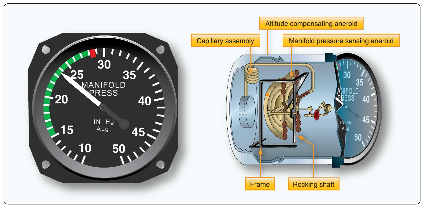
Most manifold pressure gauges are calibrated in inches of mercury, although digital displays may have the option to display in a different scale. A typical analog gauge makes use of an aneroid described above. When atmospheric pressure acts on the aneroid inside the gauge, the connected pointer indicates the current air pressure. A line running from the intake manifold into the gauge presents intake manifold air pressure to the aneroid, so the gauge indicates the absolute pressure in the intake manifold. An analog manifold pressure gauge, along with its internal workings, is shown in Figure 10-15. The digital presentation of manifold pressure is at the top of the engine instruments displayed on the Garmin G1000 multifunctional display in Figure 10-14. The aircraft’s operating manual contains data on managing manifold pressure in relation to fuel flow and propeller pitch and for achieving various performance profiles during different phases of run-up and flight.
Engine Pressure Ratio (EPR)
Turbine engines have their own pressure indication that relates the power being developed by the engine. It is called the engine pressure ratio (EPR) indicator (EPR gauge). This gauge compares the total exhaust pressure to the pressure of the ram air at the inlet of the engine. With adjustments for temperature, altitude, and other factors, the EPR gauge presents an indication of the thrust being developed by the engine. Since the EPR gauge compares two pressures, it is a differential pressure gauge. It is a remote-sensing instrument that receives its input from an engine pressure ratio transmitter or, in digital instrument systems displays, from a computer. The pressure ratio transmitter contains the bellows arrangement that compares the two pressures and converts the ratio into an electric signal used by the gauge for indication. [Figure 10-16]