
Chapter 10
Aircraft Systems
Fuel Pressure
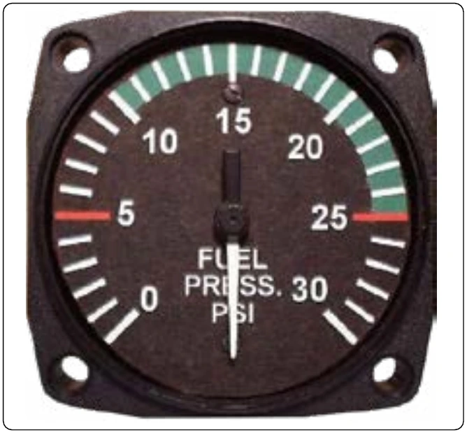
Fuel pressure gauges also provide critical information to the pilot. [Figure 10-17] Typically, fuel is pumped out of various fuel tanks on the aircraft for use by the engines. A malfunctioning fuel pump, or a tank that has been emptied beyond the point at which there is sufficient fuel entering the pump to maintain desired output pressure, is a condition that requires the pilot’s immediate attention. While direct-sensing fuel pressure gauges using Bourdon tubes, diaphragms, and bellows sensing arrangements exist, it is particularly undesirable to run a fuel line into the flight deck, due to the potential for fire should a leak develop. Therefore, the preferred arrangement is to have whichever sensing mechanism that is used be part of a transmitter device that uses electricity to send a signal to the indicator in the flight deck. Sometimes, indications monitoring the fuel flow rate are used instead of fuel pressure gauges. Fuel flow indications are discussed in the fuel system chapter of this handbook.
Hydraulic Pressure
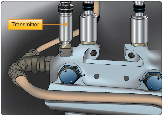
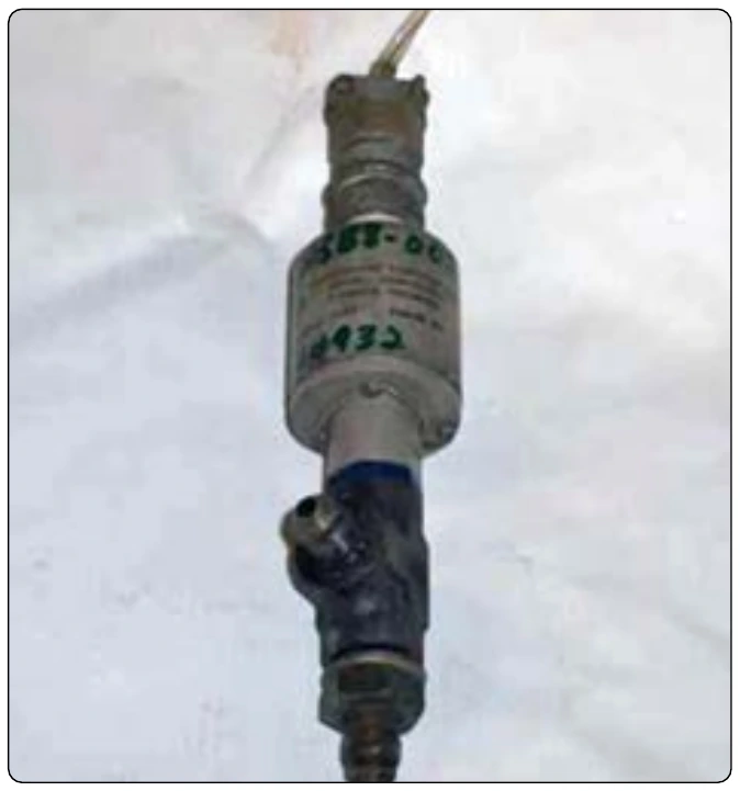
Numerous other pressure monitoring gauges are used on complex aircraft to indicate the condition of various support systems not found on simple light aircraft. Hydraulic systems are commonly used to raise and lower landing gear, operate flight controls, apply brakes, and more. Sufficient pressure in the hydraulic system developed by the hydraulic pump(s) is required for normal operation of hydraulic devices. Hydraulic pressure gauges are often located in the flight deck and at or near the hydraulic system servicing point on the airframe. Remotely located indicators used by maintenance personnel are almost always direct reading Bourdon tube type gauges. Flight deck gauges usually have system pressure transmitted from sensors or computers electrically for indication. Figure 10-18 shows a hydraulic pressure transmitter in place in a high-pressure aircraft hydraulic system.
Vacuum Pressure
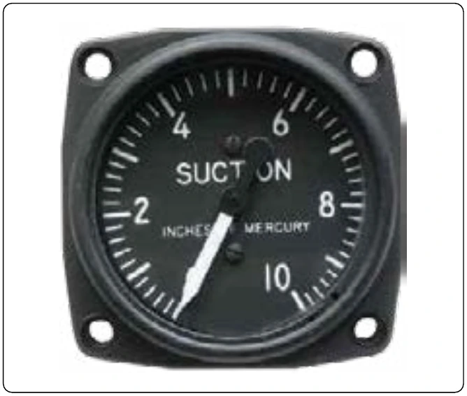
Gyro pressure gauge, vacuum gauge, or suction gauge are all terms for the same gauge used to monitor the vacuum developed in the system that actuates the air driven gyroscopic flight instruments. Air is pulled through the instruments, causing the gyroscopes to spin. The speed at which the gyros spin needs to be within a certain range for correct operation. This speed is directly related to the suction pressure that is developed in the system. The suction gauge is extremely important in aircraft relying solely on vacuum-operated gyroscopic flight instruments.
Vacuum is a differential pressure indication, meaning the pressure to be measured is compared to atmospheric pressure through the use of a sealed diaphragm or capsule. The gauge is calibrated in inches of mercury. It shows how much less pressure exists in the system than in the atmosphere. Figure 10-19 shows a suction gauge calibrated in inches of mercury.
Pressure Switches
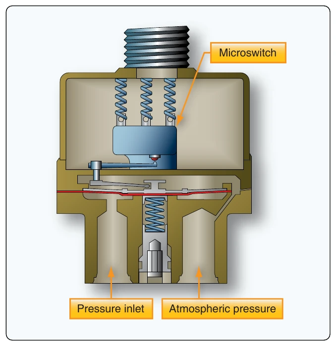
In aviation, it is often sufficient to simply monitor whether the pressure developed by a certain operating system is too high or too low, so that an action can take place should one of these conditions occur. This is often accomplished through the use of a pressure switch. A pressure switch is a simple device usually made to open or close an electric circuit when a certain pressure is reached in a system. It can be manufactured so that the electric circuit is normally open and can then close when a certain pressure is sensed, or the circuit can be closed and then opened when the activation pressure is reached. [Figure 10-20]
Pressure switches contain a diaphragm to which the pressure being sensed is applied on one side. The opposite side of the diaphragm is connected to a mechanical switching mechanism for an electric circuit. Small fluctuations or a buildup of pressure against the diaphragm move the diaphragm, but not enough to throw the switch. Only when pressure meets or exceeds a preset level designed into the structure of the switch does the diaphragm move far enough for the mechanical device on the opposite side to close the switch contacts and complete the circuit. [Figure 10-21] Each switch is rated to close (or open) at a certain pressure and must only be installed in the proper location.
A low oil pressure indication switch is a common example of how pressure switches are employed. It is installed in an engine so pressurized oil can be applied to the switch’s diaphragm. Upon starting the engine, oil pressure increases and the pressure against the diaphragm is sufficient to hold the contacts in the switch open. As such, current does not flow through the circuit and no indication of low oil pressure is given in the flight deck. Should a loss of oil pressure occur, the pressure against the diaphragm becomes insufficient to hold the switched contacts open. When the contacts close, they close the circuit to the low oil pressure indicator, usually a light, to warn the pilot of the situation.
Pressure gauges for various components or systems work similarly to those mentioned above. Some sort of sensing device, appropriate for the pressure being measured or monitored, is matched with an indicating display system. If appropriate, a properly rated pressure switch is installed in the system and wired into an indicating circuit. Further discussion of specific instruments occurs throughout this handbook as the operation of various systems and components are discussed.
Pitot-Static Systems
Some of the most important flight instruments derive their indications from measuring air pressure. Gathering and distributing various air pressures for flight instrumentation is the function of the pitot-static system.