Chapter 10
Aircraft Systems
Pointer oscillation can also occur with a mechanical indication system if the flexible drive is permitted to whip. The drive shaft should be secured at frequent intervals to prevent it from whipping. When installing mechanical type indicators, be sure that the flexible drive has adequate clearance behind the panel. Any bends necessary to route the drive should not cause strain on the instrument when it is secured to the panel. Avoid sharp bends in the drive. An improperly installed drive can cause the indicator to fail to read or to read incorrectly.
Magnetic Compass Maintenance & Compensation
The magnetic compass is a simple instrument that does not require setting or a source of power. A minimum of maintenance is necessary, but the instrument is delicate and should be handled carefully during inspection. The following items are usually included in an inspection:
- The compass indicator should be checked for correct readings on various cardinal headings and re-compensated if necessary.
- Moving parts of the compass should work easily.
- The compass bowl should be correctly suspended on an antivibration device and should not touch any part of the metal container.
- The compass bowl should be filled with liquid. The liquid should not contain any bubbles or have any discoloration. Airframe mechanics cannot refill the fluid of a whiskey compass.
- The scale should be readable and be well lit.
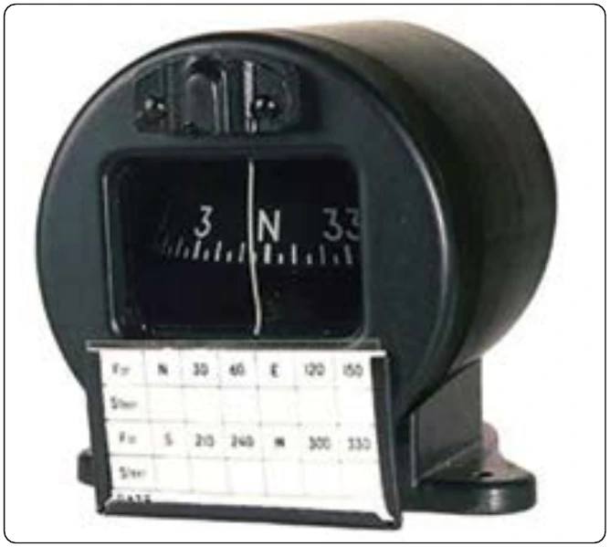
Compass magnetic deviation is caused by electromagnetic interference from ferrous materials and operating electrical components in the flight deck. Deviation can be reduced by swinging the compass and adjusting its compensating magnets. An example of how to perform this calibration process is given below. The results are recorded on a compass correction card which is placed near the compass in the flight deck. [Figure 10-139]
There are various ways to swing a compass. The following is meant as a representative method. Follow the aircraft manufacturer’s instructions for method and frequency of swinging the magnetic compass. This is usually accomplished at flight hour or calendar intervals. Compass calibration is also performed when a new electric component is added to the flight deck, such as a new radio. A complete list of conditions requiring a compass swing and procedure can be found in FAA Advisory Circular (AC) 43.13-1 (as revised), Chapter 12, Section 3, paragraph 12-37.
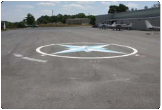
To swing a compass, a compass rose is required. Most airports have one painted on the tarmac in a low-traffic area where maintenance personnel can work. One can also be made with chalk and a good compass. The area where the compass rose is laid out should be far from any possible electromagnetic disturbances, including those underground, and should remain clear of any ferrous vehicles or large equipment while the procedure takes place. [Figure 10-140]
The aircraft should be in level flight attitude for the compass swing procedure. Tail draggers need to have the aft end of the fuselage propped up, preferably with wood, aluminum, or some other nonferrous material. The aircraft interior and baggage compartments should be free from miscellaneous items that might interfere with the compass. All normal equipment should be on board and turned on to simulate a flight condition. The engine(s) should be running.
The basic idea when swinging a compass is to note the deviation along the north-south radial and the east-west radial. Then, adjust the compensating magnets of the compass to eliminate as much deviation as possible. Begin by centering or zeroing the compass’ compensating magnets with a non-ferrous screw driver. Align the longitudinal axis of the aircraft on the N-S radial facing north. Adjust the N-S compensating screw so the indication is 0°. Next, align the longitudinal axis of the aircraft on the E-W radial facing east. Adjust the E-W compensating screw so that the compass indicates 90°. Now, move the aircraft to be aligned with the N-S radial facing south. If the compass indicates 180°, there is no deviation while the aircraft is heading due north or due south. However, this is unlikely. Whatever the south-facing indication is, adjust the N-S compensating screw to eliminate half of the deviation from 180°. Continue around to face the aircraft west on the E-W radial and use the E-W compensating screw to eliminate half of the west-facing deviation from 270°.
Once this is done, return the aircraft to alignment with the N-S radial facing north and record the indication. Up to 10° deviation is allowed. If the deviation cannot be corrected to within 10°, the compass should be replaced if further inspection reveals that there is no other reasons for this deviation. Align the aircraft with the radials every 30° around the compass rose and record each indication on the compass compensation card. Date and sign the card and place it in full view of the pilot near the compass in the flight deck.
Vacuum System Maintenance
Errors in the indication presented on a vacuum gyroscopic instrument could be the result of any factor that prevents the vacuum system from operating within the design suction limits. Errors can also be caused by problems within the instrument, such as friction, worn parts, or broken parts. Any source that disturbs the free rotation of the gyro at design speed is undesirable resulting in excessive precession and failure of the instruments to maintain accurate indication. The aircraft technician is responsible for the prevention or correction of vacuum system malfunctions. Usually this consists of cleaning or replacing filters, checking and correcting insufficient vacuum, or removing and replacing the vacuum pump or instruments. A list of the most common malfunctions, together with their correction, is included in
Autopilot System Maintenance
The information in this section does not apply to any particular autopilot system but gives general information that relates to all autopilot systems. Maintenance of an autopilot system consists of visual inspection, replacement of components, cleaning, lubrication, and an operational checkout of the system. Consult the manufacturer’s maintenance manual for all of these procedures.
With the autopilot disengaged, the flight controls should function smoothly. The resistance offered by the autopilot servos should not affect the control of the aircraft. The interconnecting mechanisms between the autopilot system and the flight control system should be correctly aligned and smooth in operation. When applicable, the operating cables should be checked for tension.
An operational check is important to assure that every circuit is functioning properly. An autopilot operational check should be performed on new installations, after replacement of an autopilot component, or whenever a malfunction in the autopilot is suspected.
After the aircraft’s main power switch has been turned on, allow the gyros to come up to speed and the amplifier to warm up before engaging the autopilot. Some systems are designed with safeguards that prevent premature autopilot engagement. While holding the control column in the normal flight position, engage the autopilot system using the switch on the autopilot controller.