
Chapter 10
Aircraft Systems
Despite their rugged outward appearance, all instruments, especially analog mechanical instruments, should be handled with special care and should never be dropped. A crack in an airtight instrument case renders it unairworthy. Ports should never be blown into and should be plugged until the instrument is installed. Cage all gyro instruments until mounted in the instrument panel. Observe all cautions written on the instrument housing and follow the manufacturer’s instruction for proper handling and shipping, as well as installation.
Instrument Installations & Markings
Instrument Panels
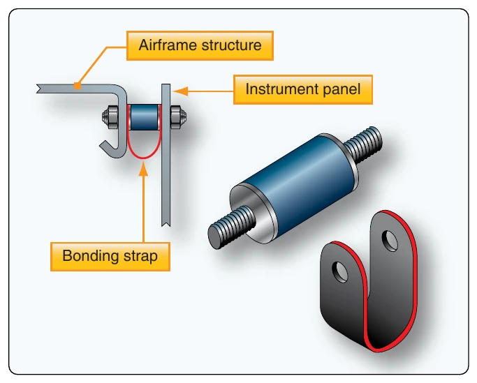
Instrument panels are usually made from sheet aluminum alloy and are painted a dark, nonglare color. They sometimes contain subpanels for easier access to the backs of instruments during maintenance. Instrument panels are usually shock-mounted to absorb low-frequency, high-amplitude shocks. The mounts absorb most of the vertical and horizontal vibration but permit the instruments to operate under conditions of minor vibration. Bonding straps are used to ensure electrical continuity from the panel to the airframe. [Figure 10-133]
The type and number of shock mounts to be used for instrument panels are determined by the weight of the unit. Shock-mounted instrument panels should be free to move in all directions and have sufficient clearance to avoid striking the supporting structure. When a panel does not have adequate clearance, inspect the shock mounts for looseness, cracks, or deterioration.
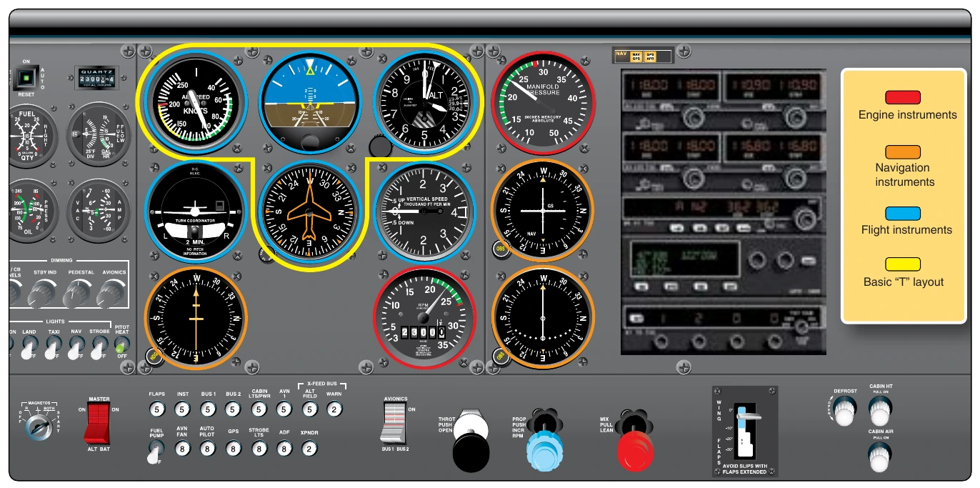
Instrument panel layout is seemingly random on older aircraft. The advent of instrument flight made the flight instruments of critical importance when flying without outside reference to the horizon or ground. As a result, the basic T arrangement for flight instruments was adopted, as mentioned in the beginning of this chapter. [Figure 10-4] Electronic flight instrument systems and digital flight deck displays have kept the same basic T arrangement for flight instrument and data presentations. The flight instruments and basic T are located directly in front of the pilot and copilot’s seats. Some light aircraft have only one full set of flight instruments that are located in front of the left seat.
The location of engine instruments and navigation instruments varies. Ideally, they should be accessible to both the pilot and copilot. Numerous variations exist to utilize the limited space in the center of the instrument panel and still provide accessibility by the flight crew to all pertinent instruments. On large aircraft, a center pedestal and overhead panels help create more space. On small aircraft, the engine instruments are often moved to allow navigation instruments and radios to occupy the center of the instrument panel. [Figure 10-134] On modern aircraft, EFIS and digital flight information systems reduce panel clutter and allow easier access to all instruments by both crewmembers. Controllable display panels provide the ability to select from pages of information that, when not displayed, are completely gone from view and use no instrument panel space.
Instrument Mounting
The method of mounting instruments in their respective panels depends on the design of the instrument case. In one design, the bezel is flanged in such a manner that the instrument can be flush mounted in its cutout from the rear of the panel. Integral, self-locking nuts are provided at the rear faces of the flange corners to receive mounting screws from the front of the panel. The flanged-type instrument can also be mounted to the front of the panel. In this case, nut-plates are usually installed in the panel itself. Nonferrous screws are usually used to mount the instruments.
There are also instrument mounting systems where the instruments are flangeless. A special clamp, shaped and dimensioned to fit the instrument case, is permanently secured to the rear face of the panel. The instrument is slid into the panel from the front and into the clamp. The clamp’s tightening screw is accessible from the front side of the panel. [Figure 10-135] Regardless of how an instrument is mounted, it should not be touching or be so close as to touch another instrument during the shock of landing.
Instrument Power Requirements
Many aircraft instruments require electric power for operation. Even nonelectric instruments may include electric lighting. Only a limited amount of electricity is produced by the aircraft’s electric generator(s). It is imperative that the electric load of the instruments, radios, and other equipment on board the aircraft does not exceed this amount.
Electric devices, including instruments, have power ratings. These show what voltage is required to correctly operate the unit and the amount of amperage it draws when operating to capacity. The rating must be checked before installing any component. Replacement of a component with one that has the same power rating is recommended to ensure the potential electric load of the installed equipment remains within the limits the aircraft manufacturer intended. Adding a component with a different rating or installing a completely new component may require a load check be performed. This is essentially an on the ground operational check to ensure the electrical system can supply all of the electricity consuming devices installed on the aircraft. Follow the manufacturer’s instructions on how to perform this check.