
Chapter 10
Aircraft Systems
Many instruments contain colored markings on the dial face to indicate, at a glance, whether a particular system or component is within a range of operation that is safe and desirable or if an undesirable condition exists. These markings are put on the instrument by the original equipment manufacturer in accordance with the Aircraft Specifications in the Type Certificate Data Sheet. Data describing these limitations can also sometimes be found in the aircraft manufacturer’s operating and maintenance manuals and in the flight manual.
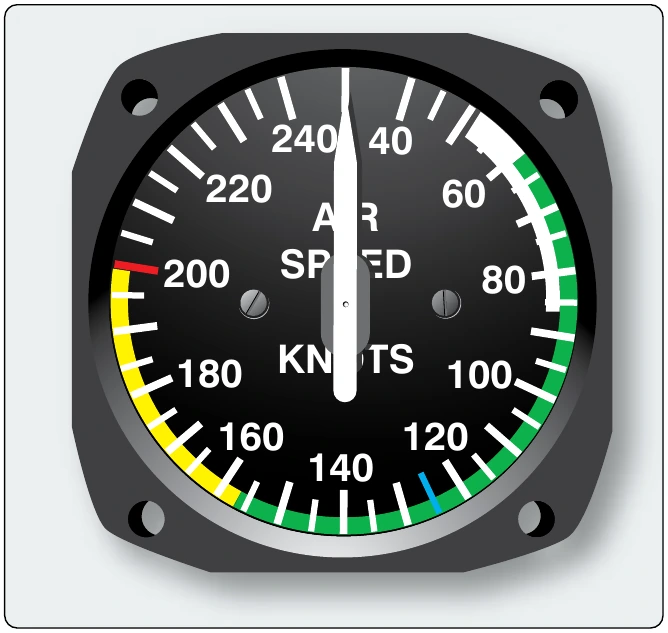
Occasionally, the aircraft technician may find it necessary to apply these marking to an approved replacement instrument on which they do not appear. It is crucial that the instrument be marked correctly and only in accordance with approved data. The marking may be placed on the cover glass of the instrument with paint or decals. A white slippage mark is made to extend from the glass to the instrument case. Should the glass rotate in the bezel, the marking will no longer be aligned properly with the calibrated instrument dial. The broken slippage mark indicates this to the pilot or technician.
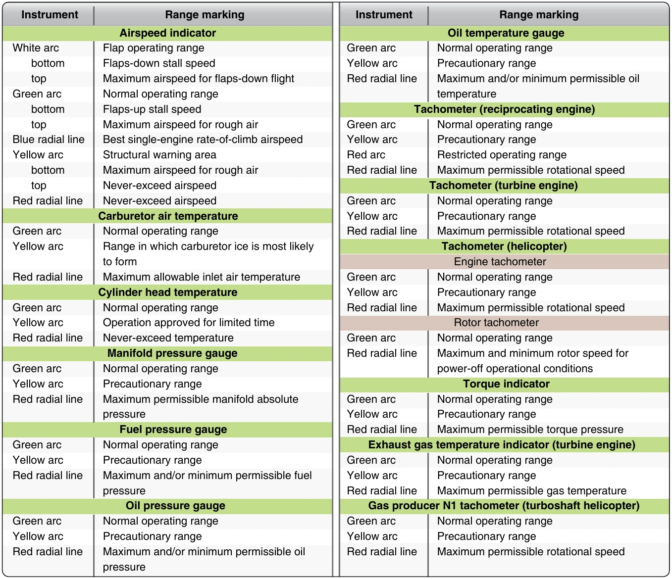
The colors used as range markings are red, yellow, green, blue, or white. The markings can be in the form of an arc or a radial line. Red is used to indicate maximum and minimum ranges; operations beyond these markings are dangerous and should be avoided. Green indicates the normal operating range. Yellow is used to indicate caution. Blue and white are used on airspeed indicators to define specific conditions. [Figures 10-136 and 10-137]
Maintenance of Instruments & Instrument Systems
An FAA airframe and powerplant (A&P) technician is not qualified to do internal maintenance on instruments and related line replaceable units discussed in this chapter. This must be carried out at facilities equipped with the specialized equipment needed to perform the maintenance properly. Qualified technicians with specialized training and intimate knowledge of instruments perform this type of work, usually under repair station certification.
However, certified airframe technicians and A&P technicians are charged with a wide variety of maintenance functions related to instruments and instrument systems. Installation, removal, inspection, troubleshooting, and functional checks are all performed in the field by certified personnel. It is also a responsibility of the certified technician holding an airframe rating to know what maintenance is required and to access the approved procedures for meeting those requirements.
In the following paragraphs, various maintenance and servicing procedures and suggestions are given. The discussion follows the order in which the various instruments and instrument systems were presented throughout this chapter. This is not meant to represent all of the maintenance required by any of the instruments or instruments systems. The aircraft manufacturer’s and instrument manufacturer’s approved maintenance documents should always be consulted for required maintenance and servicing instructions. FAA regulations must also be observed.
Altimeter Tests
When an aircraft is to be operated under IFR, an altimeter test must have been performed within the previous 24 months. Title 14 of the Code of Federal Regulations (14 CFR) part 91, section 91.411, requires this test, as well as tests on the pitot-static system and on the automatic pressure altitude reporting system. The certified airframe or A&P mechanic is not qualified to perform the altimeter inspections. They must be conducted by either the manufacturer or a certified repair station. 14 CFR part 43, Appendix E details the requirements for these tests.
Pitot-Static System Maintenance & Tests
Water trapped in a pitot static system may cause inaccurate or intermittent indications on the pitot-static flight instruments. This is especially a problem if the water freezes in flight. Many systems are fitted with drains at the low points in the system to remove any moisture during maintenance. Lacking this, dry compressed air or nitrogen may be blown through the lines of the system. Always disconnect all pitot-static instruments before doing so and always blow from the instrument end of the system towards the pitot and static ports. This procedure must be followed by a leak check described below. Systems with drains can be drained without requiring a leak check. Upon completion, the technician must ensure that the drains are closed and made secure in accordance with approved maintenance procedures.
Aircraft pitot-static systems must be tested for leaks after the installation of any component parts or when system malfunction is suspected. It must also be tested every 24 months if on an IFR certified aircraft intended to be flown as such as called out in 14 CFR part 91, section 91.411. Certified airframe and A&P technicians may perform this test.
The method of leak testing depends on the type of aircraft, its pitot-static system, and the testing equipment available. [Figure 10-138] Essentially, a testing device is connected into the static system at the static vent end, and pressure is reduced in the system by the amount required to indicate 1,000 feet on the altimeter. Then, the system is sealed and observed for 1 minute. A loss of altitude of more than 100 feet is not permissible. If a leak exists, a systematic check of portions of the system is conducted until the leak is isolated. Most leaks occur at fittings. The pitot portion of the pitot-static system is checked in a similar fashion. Follow the manufacturer’s instructions when performing all pitot-static system checks. In all cases, pressure and suction must be applied and released slowly to avoid damage to the aircraft instruments. Pitot-static system leak check units usually have their own built-in altimeters. This allows a functional cross-check of the aircraft’s altimeter with the calibrated test unit’s altimeter while performing the static system check. However, this does not meet the requirements of 14 CFR part 91, section 91.411 for altimeter tests.
Upon completion of the leak test, be sure that the system is returned to the normal flight configuration. If it is necessary to block off various portions of a system, check to be sure that all blanking plugs, adaptors, or pieces of adhesive tape have been removed.
Tachometer Maintenance
Tachometer indicators should be checked for loose glass, chipped scale markings, or loose pointers. The difference in indications between readings taken before and after lightly tapping the instrument should not exceed approximately 15 rpm. This value may vary, depending on the tolerance established by the indicator manufacturer. Both tachometer generator and indicator should be inspected for tightness of mechanical and electrical connections, security of mounting, and general condition. For detailed maintenance procedures, the manufacturer’s instructions should always be consulted.
When an engine equipped with an electrical tachometer is running at idle rpm, the tachometer indicator pointers may fluctuate and read low. This is an indication that the synchronous motor is not synchronized with the generator output. As the engine speed is increased, the motor should synchronize and register the rpm correctly. The rpm at which synchronization occurs varies with the design of the tachometer system. If the instrument pointer(s) oscillate(s) at speeds above the synchronizing value, determine that the total oscillation does not exceed the allowable tolerance.