Chapter 11
Communication & Navigation
In the early years of aviation, a compass, a map, and dead reckoning were the only navigational tools. These were marginally reassuring if weather prevented the pilot from seeing the terrain below. Voice radio transmission from someone on the ground to the pilot indicating that the aircraft could be heard overhead was a preview of what electronic navigational aids could provide. For aviation to reach fruition as a safe, reliable, consistent means of transportation, some sort of navigation system needed to be developed.
Early flight instruments contributed greatly to flying when the ground was obscured by clouds. Navigation aids were needed to indicate where an aircraft was over the earth as it progressed toward its destination. In the 1930s and 1940s, a radio navigation system was used that was a low frequency, four-course radio range system. Airports and selected navigation waypoints broadcast two Morse code signals with finite ranges and patterns. Pilots tuned to the frequency of the broadcasts and flew in an orientation pattern until both signals were received with increasing strength. The signals were received as a blended tone of the highest volume when the aircraft was directly over the broadcast area. From this beginning, numerous refinements to radio navigational aids developed.
Radio navigation aids supply the pilot with intelligence that maintains or enhances the safety of flight. As with communication radios, navigational aids are avionics devices, the repair of which must be carried out by trained technicians at certified repair stations. However, installation, maintenance and proper functioning of the electronic units, as well as their antennas, displays, and any other peripheral devices, are the responsibilities of the airframe technician.
VOR Navigation System
One of the oldest and most useful navigational aids is the very high frequency omni-directional range (VOR) navigation system. The four main components of a typical system are: a receiver, a visual indicator, a frequency selector (controller or control panel), and antennas. The system was constructed after WWII and is still in use today. It consists of thousands of land-based transmitter stations, or VORs, that communicate with radio receiving equipment on board aircraft. Many of the VORs are located along airways. The Victor airway system is built around the VOR navigation system. Ground VOR transmitter units are also located at airports where they are known as TVOR (terminal VOR). The U.S. Military has a navigational system known as TACAN that operates similarly to the VOR system. Sometimes VOR and TACAN transmitters share a location. These sites are known as VORTACs.
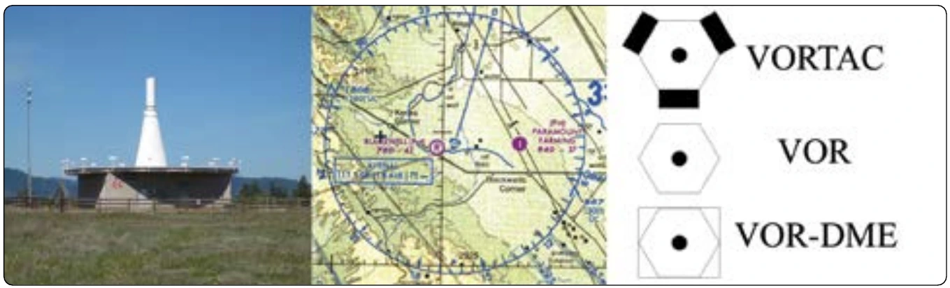
The position of all VORs, TVORs, and VORTACs are marked on aeronautical charts along with the name of the station, the frequency to which an airborne receiver must be tuned to use the station, and a Morse code designation for the station. Some VORs also broadcast a voice identifier on a separate frequency that is included on the chart. [Figure 11-95]
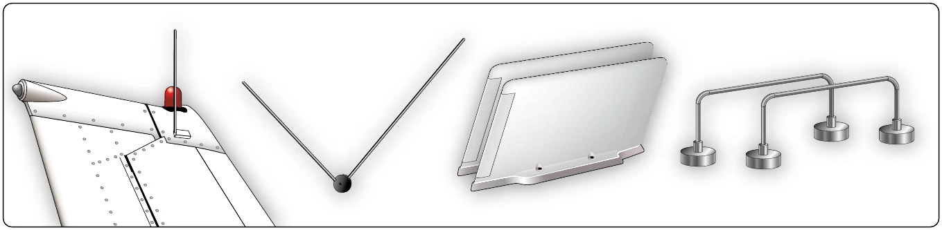
VOR uses VHF radio waves (108–117.95 MHz) with 50 kHz ([source link](https://108Œ117.95)) separation between each channel. This keeps atmospheric interference to a minimum but limits the VOR to line-of-sight usage. To receive VOR VHF radio waves, generally a V-shaped, horizontally polarized, bi-pole antenna is used. Other type antennas are also certified. Follow the manufacturer’s instructions for installation location. [Figure 11-96]
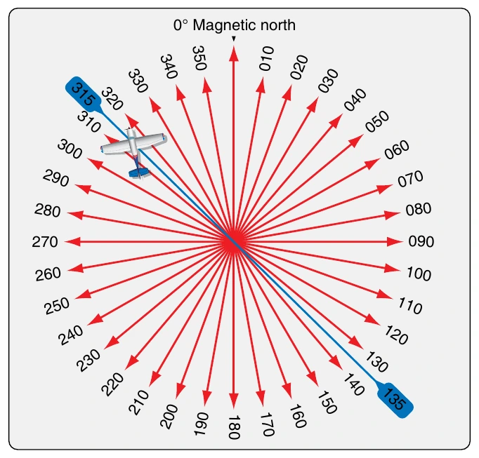
The signals produced by a VOR transmitter propagate 360° from the unit and are used by aircraft to navigate to and from the station with the help of an onboard VOR receiver and display instruments. A pilot is not required to fly a pattern to intersect the signal from a VOR station since it propagates out in every direction. The radio waves are received as long as the aircraft is in range of the ground unit and regardless of the aircraft’s direction of travel. [Figure 11-97]
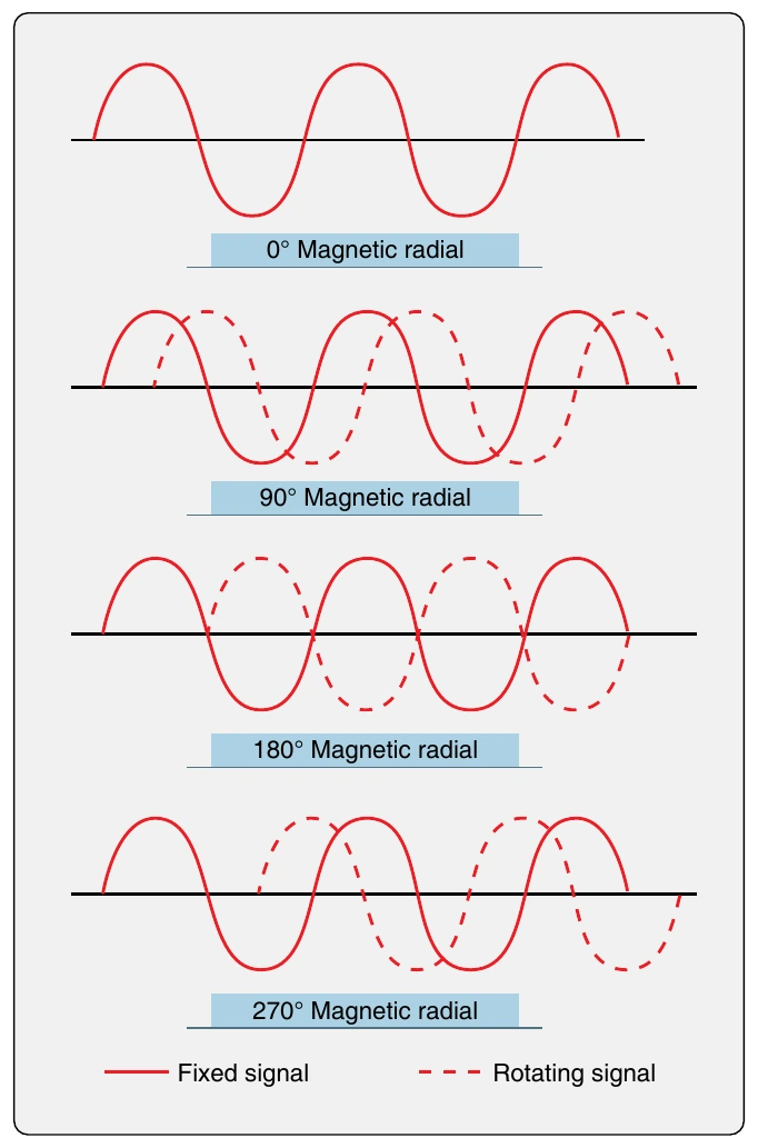
A VOR transmitter produces two signals that a receiver on board an aircraft uses to locate itself in relation to the ground station. One signal is a reference signal. The second is produced by electronically rotating a variable signal. The variable signal is in phase with the reference signal when at magnetic north but becomes increasingly out of phase as it is rotated to 180°. As it continues to rotate to 360° (0°), the signals become increasingly in phase until they are in phase again at magnetic north. The receiver in the aircraft deciphers the phase difference and determines the aircraft’s position in degrees from the VOR ground based unit. [Figure 11-98]
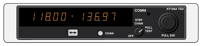
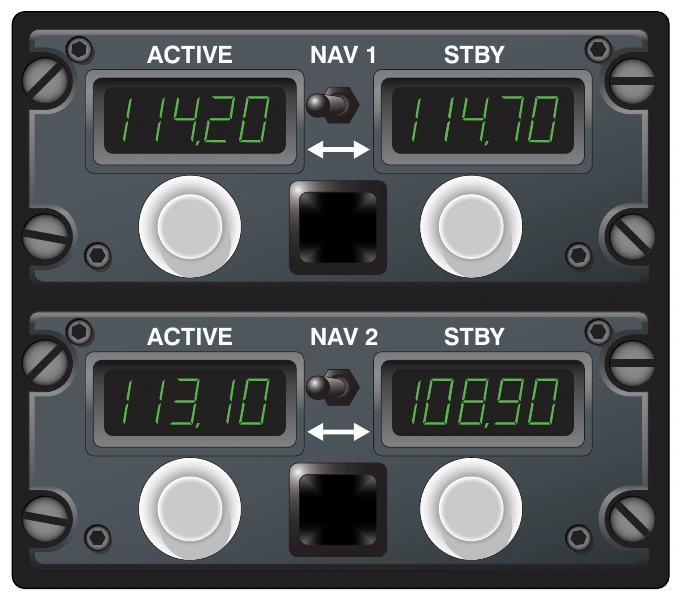
Most aircraft carry a dual VOR receiver. Sometimes, the VOR receivers are part of the same avionics unit as the VHF communication transceiver(s). These are known as NAV/COM radios. Internal components are shared since frequency bands for each are adjacent. [Figure 11-99] Large aircraft may have two dual receivers and even dual antennas. Normally, one receiver is selected for use and the second is tuned to the frequency of the next VOR station to be encountered en route. A means for switching between NAV 1 and NAV 2 is provided as is a switch for selecting the active or standby frequency. [Figure 11-100] VOR receivers are also found coupled with instrument landing system (ILS) receivers and glideslope receivers.
AVOR receiver interprets the bearing in degrees to (or from) the VOR station where the signals are generated. It also produces DC voltage to drive the display of the deviation from the desired course centerline to (or from) the selected station. Additionally, the receiver decides whether or not the aircraft is flying toward the VOR or away from it. These items can be displayed a number of different ways on various instruments. Older aircraft are often equipped with a VOR gauge dedicated to display only VOR information. This is also called an omni-bearing selector (OBS) or a course deviation indicator (CDI). [Figure 11-101]
The CDI linear indicator remains essentially vertical but moves left and right across the graduations on the instrument face to show deviation from being on course. Each graduation represents 2°. The OBS knob rotates the azimuth ring. When in range of a VOR, the pilot rotates the OBS until the course deviation indicator centers. For each location of an aircraft, the OBS can be rotated to two positions where the CDI will center. One produces an arrow in the TO window of the gauge indicating that the aircraft is traveling toward the VOR station. The other selectable bearing is 180° from this. When chosen, the arrow is displayed in the FROM window indicating the aircraft is moving away from the VOR on the course selected. The pilot must steer the aircraft to the heading with the CDI centered to fly directly to or from the VOR. The displayed VOR information is derived from deciphering the phase relationship between the two simultaneously transmitted signals from the VOR ground station. When power is lost or the VOR signal is weak or interrupted, a NAV warning flag comes into view. [Figure 11-101]