
Chapter 11
Communication & Navigation
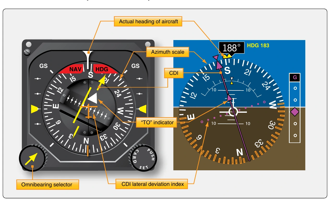
A separate gauge for the VOR information is not always used. As flight instruments and displays have evolved, VOR navigation information has been integrated into other instruments displays, such as the radio magnetic indicator (RMI), the HSI, an EFIS display or an electronic attitude director indicator (EADI). Flight management systems and automatic flight control systems are also made to integrate VOR information to automatically control the aircraft on its planned flight segments. Flat panel MFDs integrate VOR information into moving map presentations and other selected displays. The basic information of the radial bearing in degrees, course deviation indication, and to/from information remains unchanged however. [Figure 11-102]
At large airports, an instrument landing system (ILS) guides the aircraft to the runway while on an instrument landing approach. The aircraft’s VOR receiver is used to interpret the radio signals. It produces a more sensitive course deviation indication on the same instrument display as the VOR CDI display. This part of the ILS is known as the localizer and is discussed below. While tuned to the ILS localizer frequency, the VOR circuitry of the VOR/ILS receiver is inactive. It is common at VOR stations to combine the VOR transmitter with distance measuring equipment (DME) or a nondirectional beacon (NDB) such as an ADF transmitter and antenna. When used with a DME, pilots can gain an exact fix on their location using the VOR and DME together. Since the VOR indicates the aircraft’s bearing to the VOR transmitter and a co-located DME indicates how far away the station is, this relieves the pilot from having to fly over the station to know with certainty their location. These navigational aids are discussed separately in the following sections.
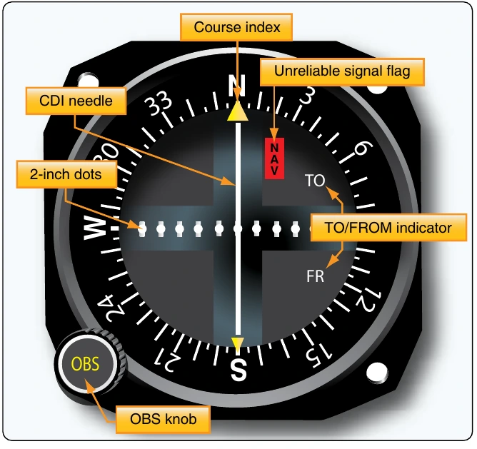
Functional accuracy of VOR equipment is critical to the safety of flight. VOR receivers are operationally tested using VOR test facilities (VOT). These are located at numerous airports the area concerned. Specific points on the airport surface are given to perform the test. Most VOTs require tuning 108.0 MHz on the VOR receiver and centering the CDI. The OBS should indicate 0° showing FROM on the indicator or 180° when showing TO. If an RMI is used as the indicator, the test heading should always indicate 180°. Some repair stations can also generate signals to test VOR receivers although not on 108.0 MHz. Contact the repair station for the transmission frequency and for their assistance in checking the VOR system. A logbook entry is required.
system with a VOT. An error in excess of this prevents the use of the aircraft for IFR fight until repairs are made. Aircraft having dual VOR systems where only the antenna is shared may be tested by comparing the output of each system to the other. Tune the VOR receivers to the local ground VOR
Automatic Direction Finder (ADF)
An automatic direction finder (ADF) operates off of a ground signal transmitted from a NDB. Early radio direction finders (RDF) used the same principle.A vertically polarized antenna was used to transmit LF frequency radio waves in the 190 kHz to 535 kHz range. A receiver on the aircraft was tuned to the transmission frequency of the NDB. Using a loop antenna, the direction to (or from) the antenna could be determined by monitoring the strength of the signal received. This was possible because a radio wave striking a loop antenna broadside induces a null signal. When striking it in the plane of the loop, a much stronger signal is induced. The NDB signals were modulated with unique Morse code pulses that enabled the pilot to identify the beacon to which they were navigating.
With RDF systems, a large rigid loop antenna was installed inside the fuselage of the aircraft. The broadside of the antenna was perpendicular to the aircraft’s longitudinal axis. The pilot listened for variations in signal strength of the LF broadcast and maneuvered the aircraft so a gradually increasing null signal was maintained. This took them to the transmitting antenna. When over flown, the null signal gradually faded as the aircraft became farther from the station. The increasing or decreasing strength of the null signal was the only way to determine if the aircraft was flying to or from the NDB. A deviation left or right from the course caused the signal strength to sharply increase due to the loop antenna’s receiving properties.
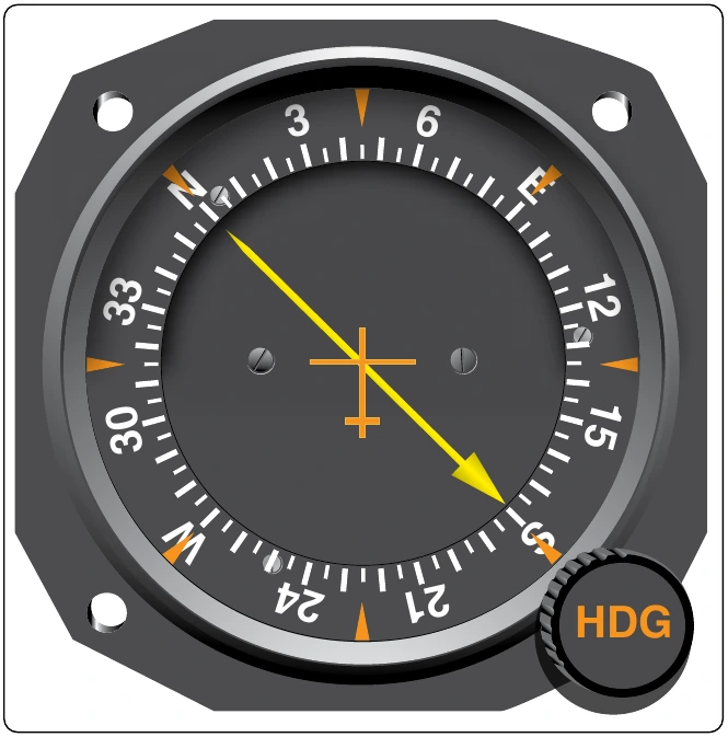
The ADF improved on this concept. The broadcast frequency range was expanded to include MF up to about 1800 kHz. The heading of the aircraft no longer needed to be changed to locate the broadcast transmission antenna. In early model ADFs, a rotatable antenna was used instead. The antenna rotated to seek the position in which the signal was null. The direction to the broadcast antenna was shown on an azimuth scale of an ADF indicator in the flight deck. This type of instrument is still found in use today. It has a fixed card with 0° always at the top of a non-rotating dial. A pointer indicates the relative bearing to the station. When the indication is 0°, the aircraft is on course to (or from) the station. [Figure 11-103]
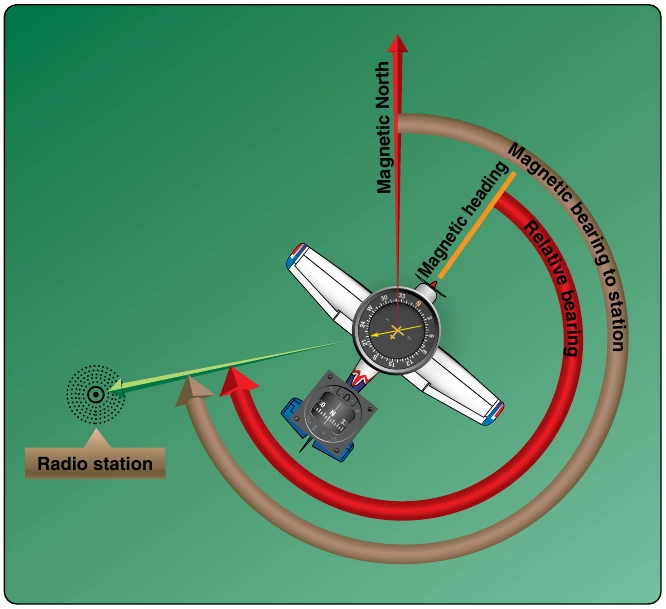
As ADF technology progressed, indicators with rotatable azimuth cards became the norm. When an ADF signal is received, the pilot rotates the card so that the present heading is at the top of the scale. This results in the pointer indicating the magnetic bearing to the ADF transmitter. This is more intuitive and consistent with other navigational practices. [Figure 11-104]
In modern ADF systems, an additional antenna is used to remove the ambiguity concerning whether the aircraft is heading to or from the transmitter. It is called a sense antenna. The reception field of the sense antenna is omnidirectional. When combined with the fields of the loop antenna, it forms a field with a single significant null reception area on one side. This is used for tuning and produces an indication in the direction toward the ADF station at all times. The onboard ADF receiver needs only to be tuned to the correct frequency of the broadcast transmitter for the system to work. The loop and sense antenna are normally housed in a single, low profile antenna housing. [Figure 11-105]
Any ground antenna transmitting LF or MF radio waves in range of the aircraft receiver’s tuning capabilities can be used for ADF. This includes those from AM radio stations. Audible identifier tones are loaded on the NDB carrier waves. Typically, a two-character Morse code designator is used. With an AM radio station transmission, the AM broadcast is heard instead of a station identifier code. The frequency for an NDB transmitter is given on an aeronautical chart next to a symbol for the transmitter. The identifying designator is also given. [Figure 11-106]
ADF receivers can be mounted in the flight deck with the controls accessible to the user. This is found on many general aviation aircraft. Alternately, the ADF receiver is mounted in a remote avionics bay with only the control head in the flight deck. DualADF receivers are common. ADF information can be displayed on the ADF indicators mentioned or it can be digital. Modern, flat, multipurpose electronic displays usually display the ADF digitally. [Figure 11-107] When ANT is selected on an ADF receiver, the loop antenna is cut out and only the sense antenna is active. This provides better multi-directional reception of broadcasts in the ADF frequency range, such as weather or AWAS broadcasts.
When the best frequency oscillator (BFO) is selected on an ADF receiver/controller, an internal beat frequency oscillator is connected to the IF amplifier inside the ADF receiver. This is used when an NDB does not transmit a modulated signal.