
Chapter 11
Communication & Navigation
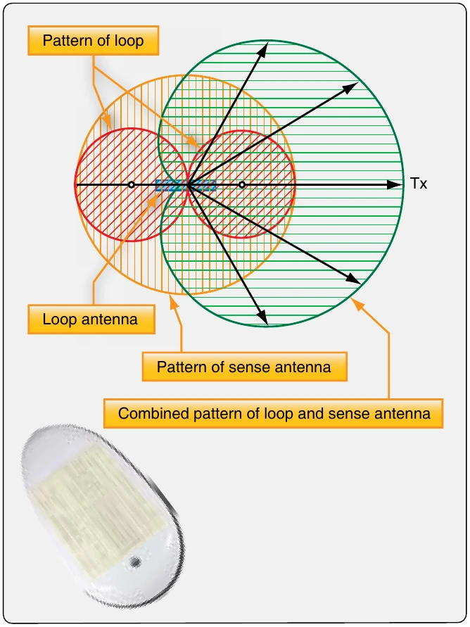
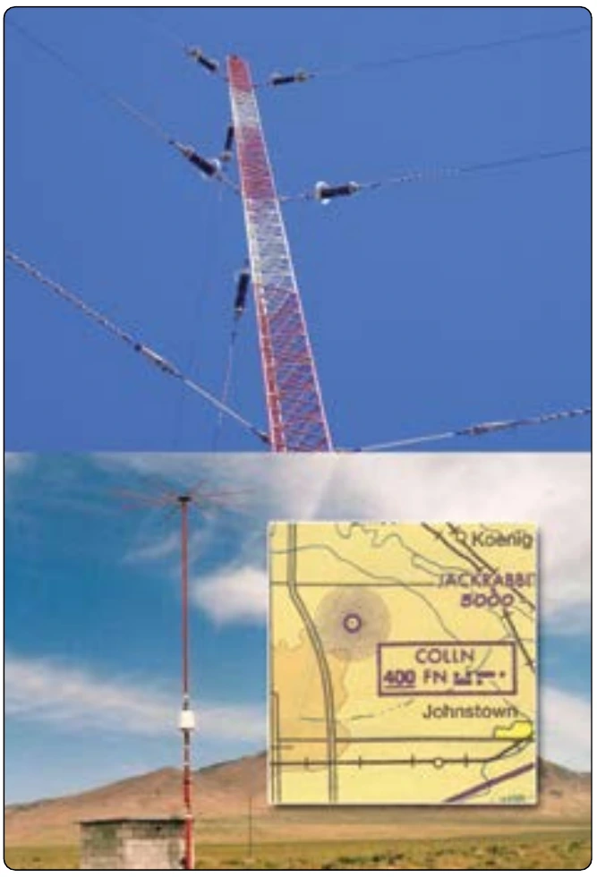
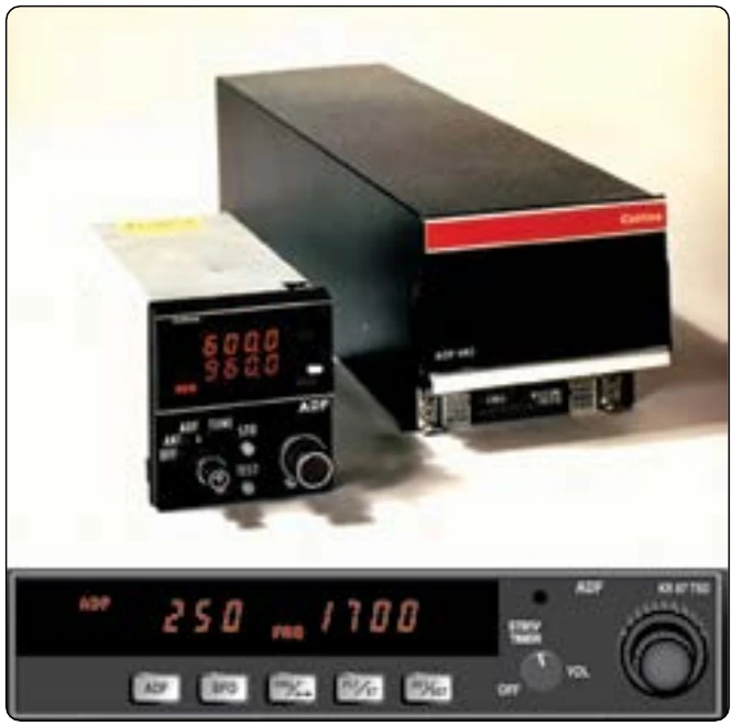
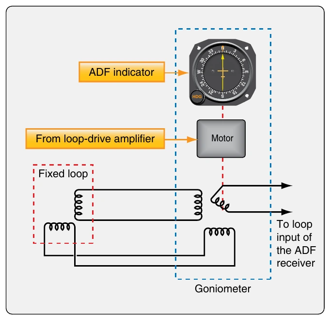
Continued refinements to ADF technology has brought it to its current state. The rotating receiving antenna is replaced by a fixed loop with a ferrite core. This increases sensitivity and allows a smaller antenna to be used. The most modern ADF systems have two loop antennas mounted at 90° to each other. The received signal induces voltage that is sent to two stators in a resolver or goniometer. The goniometer stators induce voltage in a rotor that correlates to the signal of the fixed loops. The rotor is driven by a motor to seek the null. The same motor rotates the pointer in the flight deck indicator to show the relative or magnetic bearing to the station. [Figure 11-108]
Technicians should note that the installation of the ADF antenna is critical to a correct indication since it is a directional device. Calibration with the longitudinal axis of the fuselage or nose of the aircraft is important. A single null reception area must exist in the correct direction. The antenna must be oriented so the ADF indicates station location when the aircraft is flying toward it rather than away. Follow all manufacturer’s instructions.
Radio Magnetic Indicator (RMI)
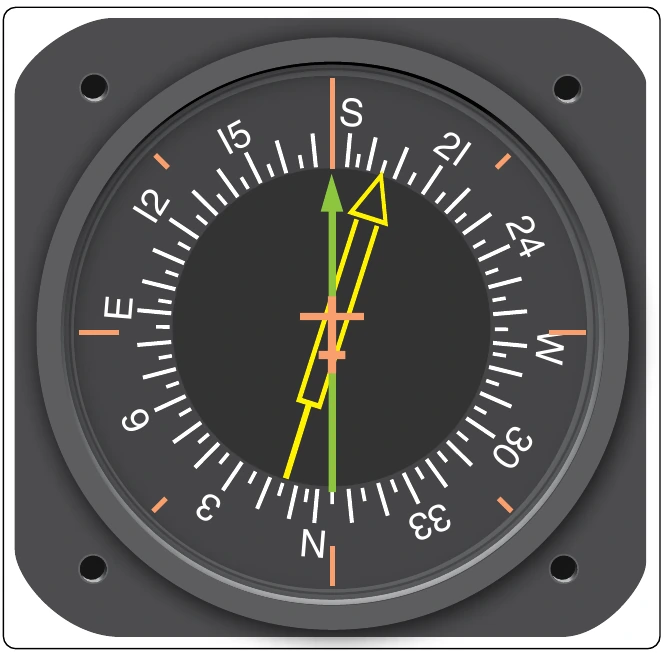
To save space in the instrument panel and to consolidate related information into one easy to use location, the radio magnetic indicator (RMI) has been developed. It is widely used. The RMI combines indications from a magnetic compass, VOR, and ADF into one instrument. [Figure 11-109]
The azimuth card of the RMI is rotated by a remotely located flux gate compass. Thus, the magnetic heading of the aircraft is always indicated. The lubber line is usually a marker or triangle at the top of the instrument dial. The VOR receiver drives the solid pointer to indicate the magnetic direction TO a tuned VOR station. When the ADF is tuned to an NDB, the double, or hollow pointer, indicates the magnetic bearing to the NDB.
Since the flux gate compass continuously adjusts the azimuth card so that the aircraft heading is at the top of the instrument, pilot workload is reduced. The pointers indicate where the VOR and ADF transmission stations are located in relationship to where the aircraft is currently positioned. Push buttons allow conversion of either pointer to either ADF or VOR for navigation involving two of one type of station and none of the other.
Instrument Landing Systems (ILS)
An ILS is used to land an aircraft when visibility is poor. This radio navigation system guides the aircraft down a slope to the touch down area on the runway. Multiple radio transmissions are used that enable an exact approach to landing with an ILS. A localizer is one of the radio transmissions. It is used to provide horizontal guidance to the center line of the runway. A separate glideslope broadcast provides vertical guidance of the aircraft down the proper slope to the touch down point. Compass locator transmissions for outer and middle approach marker beacons aid the pilot in intercepting the approach navigational aid system. Marker beacons provide distance-from-the-runway information. Together, all of these radio signals make an ILS a very accurate and reliable means for landing aircraft. [Figure 11-110]
Localizer
The localizer broadcast is a VHF broadcast in the lower range of the VOR frequencies (108 MHz–111.95 MHz) on ([source link](https://MHzŒ111.95)) odd frequencies only. Two modulated signals are produced from a horizontally polarized antenna complex beyond the far end of the approach runway. They create an expanding field that is 21⁄2° wide (about 1,500 feet) 5 miles from the runway. The field tapers to runway width near the landing threshold. The left side of the approach area is filled with a VHF carrier wave modulated with a 90 Hz signal. The right side of the approach contains a 150 MHz modulated signal. The aircraft’s VOR receiver is tuned to the localizer VHF frequency that can be found on published approach plates and aeronautical charts.
The circuitry specific to standard VOR reception is inactive while the receiver uses localizer circuitry and components common to both. The signals received are passed through filters and rectified into DC to drive the course deviation indicator. If the aircraft receives a 150 Hz signal, the CDI of the VOR/ILS display deflects to the left. This indicates that the runway is to the left. The pilot must correct course with a turn to the left. This centers the course deviation indicator on the display and centers the aircraft with the centerline of the runway. If the 90 Hz signal is received by the VOR receiver, the CDI deflects to the right. The pilot must turn toward the right to center the CDI and the aircraft with the runway center line. [Figure 11-111]
Glideslope
The vertical guidance required for an aircraft to descend for a landing is provided by the glideslope of the ILS. The glideslope provides vertical guidance for correct angle of descent. Radio signals funnel the aircraft down to the touchdown point on the runway at an angle of approximately 3°. The transmitting glideslope antenna is located off to the side of the approach runway approximately 1,000 feet from the threshold. It transmits in a wedge-like pattern with the field narrowing as it approaches the runway. [Figure 11-112]
The glideslope transmitter antenna is horizontally polarized. The transmitting frequency range is UHF between 329.3 MHz and 335.0 MHz. The frequency is paired to the localizer frequency of the ILS. When the VOR/ILS receiver is tuned for the approach, the glideslope receiver is automatically tuned. Like the localizer, the glideslope transmits two signals, one modulated at 90 Hz and the other modulated at 150 Hz. The aircraft’s glideslope receiver deciphers the signals similar to the method of the localizer receiver. It drives a vertical course deviation indicator known as the glideslope indicator. The glideslope indicator operates identically to the localizer CDI only 90° to it. The VOR/ILS localizer CDI and the glideslope are displayed together on whichever kind of instrumentation is in the aircraft. [Figure 11-113]
The UHF antenna for aircraft reception of the glideslope signals comes in many forms. A single dipole antenna mounted inside the nose of the aircraft is a common option. Antenna manufacturers have also incorporated glideslope reception into the same dipole antenna used for the VHS VOR/ILS localizer reception. Blade type antennas are also used. [Figures 11-114] Figure 11-115 shows a VOR and a glideslope receiver for a GA aircraft ILS.