Chapter 11
Communication & Navigation
Electronic devices represent and manipulate real-world phenomenon through the use of electrical signals. Electronic circuits are designed to perform a wide array of manipulations. Analog representations are continuous. Some aspect of an electric signal is modified proportionally to the real-world item that is being represented. For example, a microphone has electricity flowing through it that is altered when sound is applied. The type and strength of the modification to the electric signal is characteristic of the sound that is made into the microphone. The result is that sound, a real-world phenomenon, is represented electronically. It can then be moved, amplified, and reconverted from an electrical signal back into sound and broadcast from a speaker across the room or across the globe.
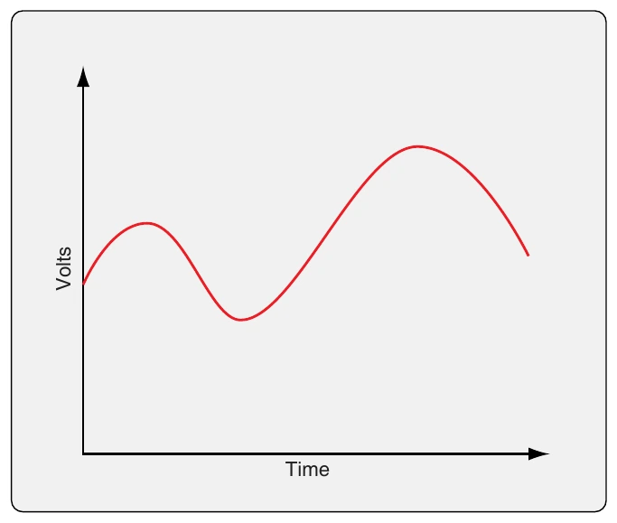
Since the flow of electricity through the microphone is continuous, the sound continuously modifies the electric signal. On an oscilloscope, an analog signal is a continuous curve. [Figure 11-3] An analog electric signal can be modified by changing the signal’s amplitude, frequency, or phase.
A digital electronic representation of a real-world event is discontinuous. The essential characteristics of the continuous event are captured as a series of discrete incremental values. Electronically, these representative samplings are successive chains of voltage and non-voltage signals. They can be transported and manipulated in electronic circuits. When the samples are sufficiently small and occur with high frequency, real-world phenomenon can be represented to appear continuous.
Noise
A significant advantage of digital electronics over analog electronics is the control of noise. Noise is any alteration of the represented real-world phenomenon that is not intended or desired. Consider the operation of a microphone when understanding noise. A continuous analog voltage is modified by a voice signal that results in the continuous voltage varying in proportion to the volume and tone of the input sound. However, the voltage responds and modifies to any input. Thus, background sounds also modify the continuous voltage as will electrostatic activity and circuitry imperfections. This alteration by phenomenon that are not the intended modifier is noise.
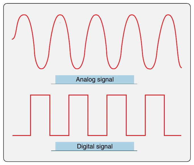
During the processing of digitized data, there is little or no signal degradation. The real-world phenomenon is represented in a string of binary code. A series of ones and zeros are electronically created as a sequence of voltage or no voltage and carried through processing stages. It is relatively immune to outside alteration once established. If a signal is close to the set value of the voltage, it is considered to be that voltage. If the signal is close to zero, it is considered to be no voltage. Small variations or modifications from undesired phenomenon are ignored. Figure 11-4 illustrates an analog sine wave and a digital sine wave. Any unwanted voltage will modify the analog curve. The digital steps are not modified by small foreign inputs. There is either voltage or no voltage.
Analog Electronics
Early aircraft were equipped with radio communication and navigational devices that were constructed with analog electronic circuits. They used vacuum tubes that functioned as electron control valves. These were later replaced by solid-state devices. Today, digital electronic circuits dominate modern avionics. A brief look at various electron control valves used on aircraft follows.
Electron Control Valves
Electron control valves are an essential part of an electronic circuit. Control of electron flow enables the circuit to produce the desired outcome. Early aircraft made use of vacuum tubes to control electron flow. Later, transistors replaced vacuum tubes. Semiconductors used in transistors and integrated circuits have enabled the solid-state digital electronics found in aircraft today.
Vacuum Tubes
Electron control valves found in the analog circuits of early aircraft electronics are constructed of vacuum tubes. Only antique aircraft retain radios with these devices due to their size and inability to withstand the harsh vibration and shock of the aircraft operating environment. However, they do function, and a description is included here as a foundation for the study of more modern electronic circuits and components.
Diodes
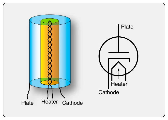
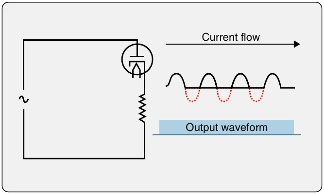
A diode acts as a check valve in an alternating current (AC) circuit. It allows current to flow during half of the AC cycle but not the other half. In this manner, it creates a pulsating direct current (DC) with current that drops to zero in between pulses. A diode tube has two active electrodes: the cathode and the plate. It also contains a heater. All of this is housed in a vacuum environment inside the tube. [Figure 11-5] The heater glows red hot while heating the cathode. The cathode is coated with a material whose electrons are excited by the heat. The excited electrons expand their orbit when heated. They move close enough to the plate, which is constructed around the cathode and heater arrangement, that they are attracted to the positively-charged plate. When the AC current cycles, the plate becomes negatively charged and the excited cathode electrons do not flow to the plate. In a circuit, this causes a check valve effect that allows current to only flow in one direction, which is the definition of a diode. [Figure 11-6] The various symbols used to depict diodes are shown in Figure 11-7.
Triodes
A triode is an electron control valve containing three elements. It is often used to control a large amount of current with a smaller current flow. In addition to the cathode, plate, and heater present in the diode, a triode also contains a grid. The grid is composed of fine wire spiraled between the cathode and the plate but closer to the cathode. Applying voltage to the grid can influence the cathode’s electrons, which normally flow to the plate when the cathode is heated. Changes in the relatively small amount of current that flows through the grid can greatly impact the flow of electrons from the cathode to the plate. [Figure 11-8]