
Chapter 11
Communication & Navigation
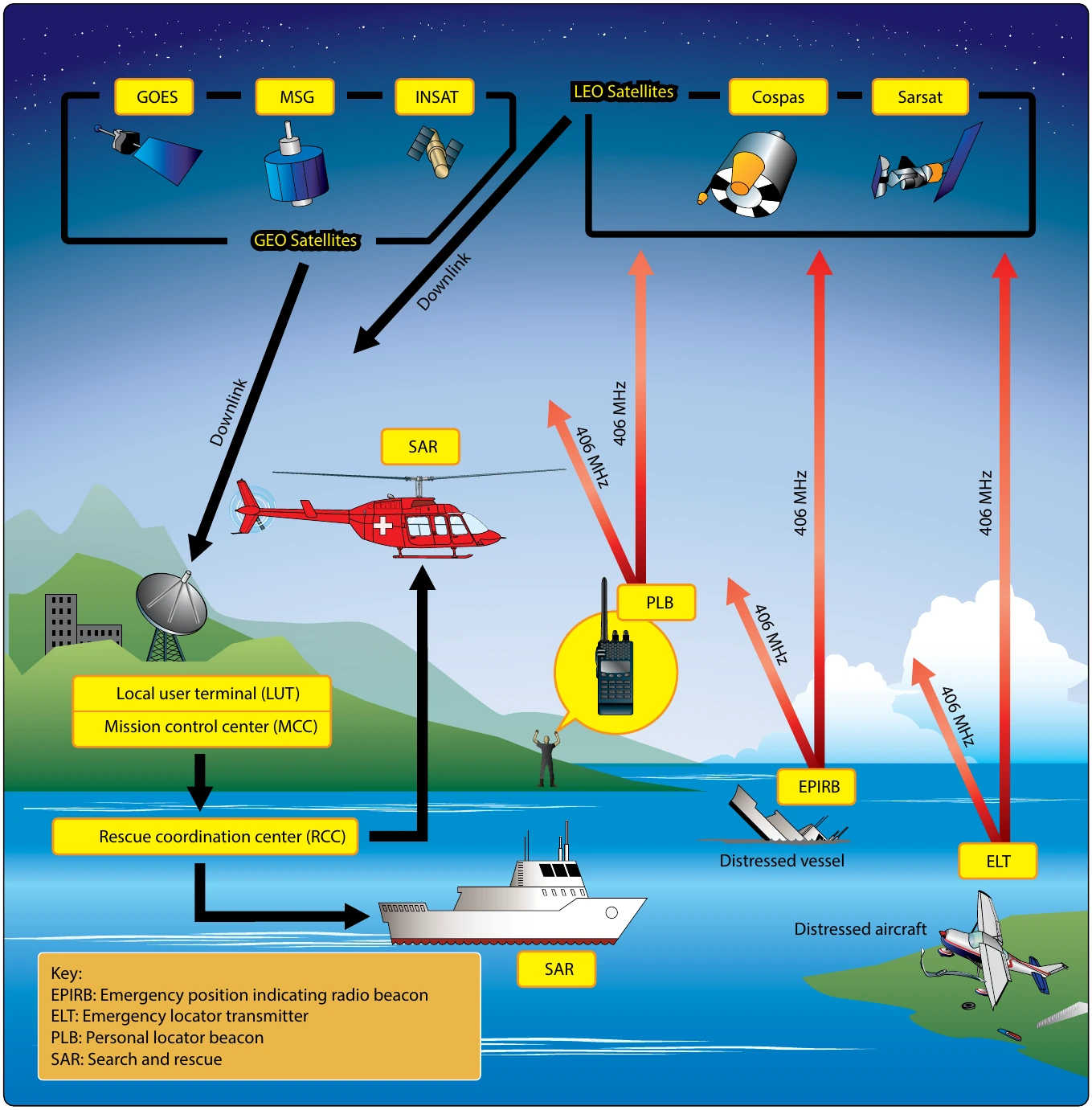
Testing an ELT system in a metal hangar will not guarantee the radiated signal will not be detected by the Cospas-Sarsat System. Technicians testing ELT devices in a hangar should treat the test as if they were testing outside.
When testing an ELT, a 50-ohm dummy load or antenna boot should be used to prevent the signal from being radiated into space. The signal must be attenuated to less than -51 dBW (a power flux density of -37.4 dB (W/m2) or a field intensity of -11.6 dB (V/m).
If over-air testing must be accomplished, technicians should carefully follow Cospas-Sarsat instructions and use the built-in test message on the ELT device. The ELT test message is different from messages transmitted during an emergency, but is still detectable by the Cospas-Sarsat System. Cospas-Sarsat should be contacted prior to performing over-air testing. Cospas-Sarsat can be contacted at [www.cospas-sarsat.int/en/](https://www.cospas-sarsat.int/en/). If over-air testing must be accomplished, the local air traffic control (ATC) facility should be contacted in advance.
Follow test set instructions or place the test set a minimum of 12 meters, (39.4 feet) from the ELT antenna. Test in each mode and frequency the ELT unit transmits.
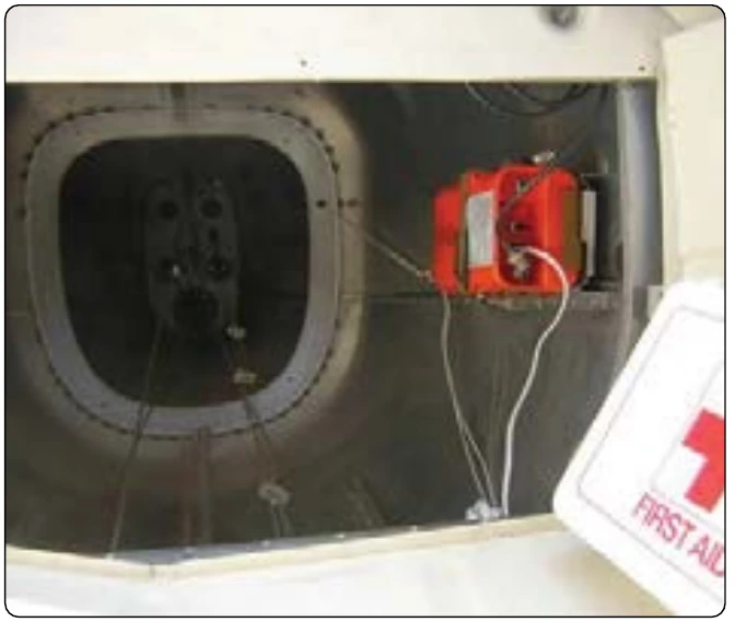
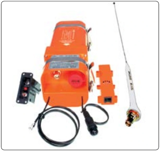
406 MHz Testing
Verify the device is outputting a signal of not less than 17 dBm (50 mW) and not greater than 26 dBm (400 mW).
Verify the device is transmitting on the correct frequency. This can be done by running the ELT self-test and detecting the signal with an ELT test set. Receiving and decoding a test message is an indication the unit is transmitting on a correct frequency.
Using appropriate test equipment and shielding, note the ELT code transmitted and verify that the ELT code is registered with Cospas-Sarsat. The testing technician or aircraft owner should verify the information on file with Cospas-Sarsat is accurate and up to date.
Determine that the ELT aural indicator can be heard in the flight deck with the aircraft engine(s) off, and that the visual indicator can be seen from the crew’s normal sitting position. If possible, this should be performed in a way that will prevent a SAR response (e.g., with a dummy load installed).
Perform an operational check of the g switch. This should be performed in a way that will prevent a SAR response (e.g., with a dummy load installed). Replace if the g switch fails to activate.
Ensure all cables except the 406 MHz transmitter output are reconnected. Ensure the 406 MHz transmitter is connected to a test set if possible. Activate the ELT (use the remote switch if installed), and determine if the system is radiating a strong 406 MHz signal. Ensure the system is reset if necessary.
If equipped with a water-activated circuit, connect the ELT to a test set if possible. Activate the ELT by shorting the water-sensing leads and determine if the system is radiating a strong 406 MHz signal. Ensure the system is reset if necessary.
Long Range Aid to Navigation System (LORAN)
Long range aid to navigation system (LORAN) is a type of RNAV that is no longer available in the United States. It was developed during World War II, and the most recent edition, LORAN-C, has been very useful and accurate to aviators as well as maritime sailors. LORAN uses radio wave pulses from a series of towers and an on-board receiver/computer to positively locate an aircraft amid the tower network. There are twelve LORAN transmitter tower “chains” constructed across North America. Each chain has a master transmitter tower and a handful of secondary towers. All broadcasts from the transmitters are at the same frequency, 100 KHz. Therefore, a LORAN receiver does not need to be tuned. Being in the low frequency range, the LORAN transmissions travel long distances and provide good coverage from a small number of stations.
Precisely-timed, synchronized pulse signals are transmitted from the towers in a chain. The LORAN receiver measures the time to receive the pulses from the master tower and two other towers in the chain. It calculates the aircraft’s position based on the intersection of parabolic curves representing elapsed signal times from each of these known points.
The accuracy and proliferation of GPS navigation has caused the U.S. Government to cease support for the LORAN navigation system citing redundancy and expense of operating the towers as reasons. Panel-mounted LORAN navigation units will likely be removed and replaced by GPS units in aircraft that have not already done so. [Figure 11-151]