Chapter 11
Communication & Navigation
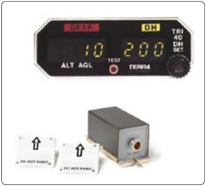
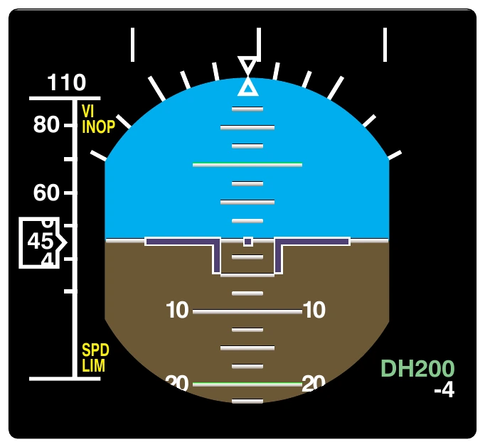
Large aircraft may incorporate radio altimeter information into a ground proximity warning system (GPWS) which aurally alerts the crew of potentially dangerous proximity to the terrain below the aircraft. A decision height (DH) window displays the radar altitude on the EADI in Figure 11-141.
Weather Radar
There are three common types of weather aids used in an aircraft flight deck that are often referred to as weather radar:
- Actual on-board radar for detecting and displaying weather activity;
- Lightning detectors; and
- Satellite or other source weather radar information that is uploaded to the aircraft from an outside source.
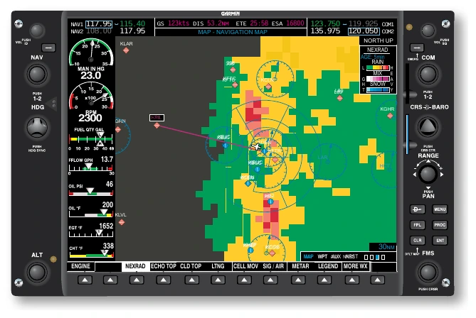
On-board weather radar systems can be found in aircraft of all sizes. They function similar to ATC primary radar except the radio waves bounce off of precipitation instead of aircraft. Dense precipitation creates a stronger return than light precipitation. The on-board weather radar receiver is set up to depict heavy returns as red, medium returns as yellow and light returns as green on a display in the flight deck. Clouds do not create a return. Magenta is reserved to depict intense or extreme precipitation or turbulence. Some aircraft have a dedicated weather radar screen. Most modern aircraft integrate weather radar display into the navigation display(s). Figure 11-142 illustrates weather radar displays found on aircraft.
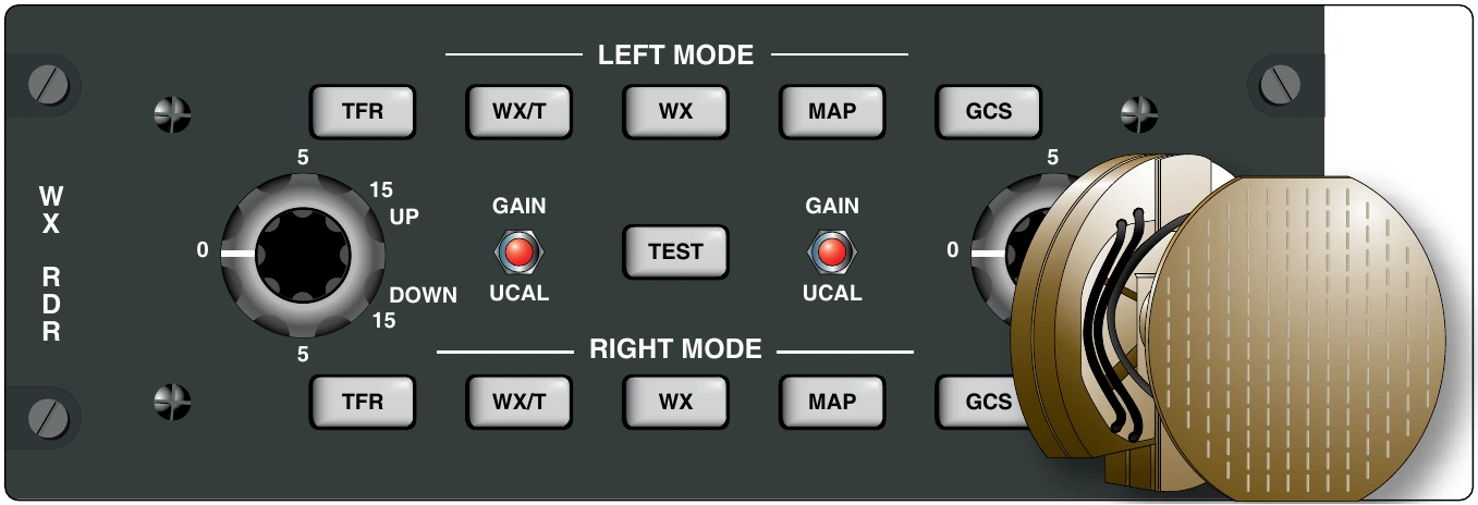
Radio waves used in weather radar systems are in the SHF range such as 5.44 GHz or 9.375 GHz. They are transmitted forward of the aircraft from a directional antenna usually located behind a non-metallic nose cone. Pulses of approximately 1 micro-second in length are transmitted. A duplexer in the radar transceiver switches the antenna to receive for about 2,500 micro seconds after a pulse is transmitted to receive and process any returns. This cycle repeats and the receiver circuitry builds a two dimensional image of precipitation for display. Gain adjustments control the range of the radar. A control panel facilitates this and other adjustments. [Figure 11-143]
Severe turbulence, windshear, and hail are of major concern to the pilot. While hail provides a return on weather radar, windshear and turbulence must be interpreted from the movement of any precipitation that is detected. An alert is annunciated if this condition occurs on a weather radar system so equipped. Dry air turbulence is not detectable. Ground clutter must also be attenuated when the radar sweep includes any terrain features. The control panel facilitates this.
Special precautions must be followed by the technician during maintenance and operation of weather radar systems. The radome covering the antenna must only be painted with approved paint to allow the radio signals to pass unobstructed. Many radomes also contain grounding strips to conduct lightning strikes and static away from the dome.
When operating the radar, it is important to follow all manufacturer instructions. Physical harm is possible from the high energy radiation emitted, especially to the eyes and testes. Do not look into the antenna of a transmitting radar. Operation of the radar should not occur in hangars unless special radio wave absorption material is used. Additionally, operation of radar should not take place while the radar is pointed toward a building or when refueling takes place. Radar units should be maintained and operated only by qualified personnel.
Lightning detection is a second reliable means for identifying potentially dangerous weather. Lightning gives off its own electromagnetic signal. The azimuth of a lightning strike can be calculated by a receiver using a loop type antenna such as that used in ADF. [Figure 11-144] Some lightning detectors make use of the ADF antenna. The range of the lightning strike is closely associated with its intensity. Intense strikes are plotted as being close to the aircraft.
Stormscope is a proprietary name often associated with lightning detectors. There are others that work in a similar manner. A dedicated display plots the location of each strike within a 200 mile range with a small mark on the screen. As time progresses, the marks may change color to indicate their age. Nonetheless, a number of lightning strikes in a small area indicates a storm cell, and the pilot can navigate around it. Lightning strikes can also be plotted on a multifunctional navigation display. [Figure 11-145]
A third type of weather radar is becoming more common in all classes of aircraft. Through the use of orbiting satellite systems and/or ground up-links, such as described with ADS-B IN, weather information can be sent to an aircraft in flight virtually anywhere in the world. This includes text data as well as real-time radar information for overlay on an aircraft’s navigational display(s). Weather radar data produced remotely and sent to the aircraft is refined through consolidation of various radar views from different angles and satellite imagery. This produces more accurate depictions of actual weather conditions. Terrain databases are integrated to eliminate ground clutter. Supplemental data includes the entire range of intelligence available from the National Weather Service (NWS) and the National Oceanographic and Atmospheric Administration (NOAA). Figure 11-146 illustrates a plain language weather summary received in an aircraft along with a list of other weather information available through satellite or ground link weather information services.