
Chapter 12
Hydraulic & Pneumatic Power Systems
As the piston begins to withdraw from the cylinder block, system inlet pressure forces fluid through a porting arrangement in the valve plate into the cylinder bore. The piston shoes are restrained in the yoke by a piston shoe retaining plate and a shoe plate during the intake stroke. As the drive shaft continues to turn the cylinder block, the piston shoe continues following the yoke bearing surface. This begins to return the piston into its bore (i.e., toward the valve block).
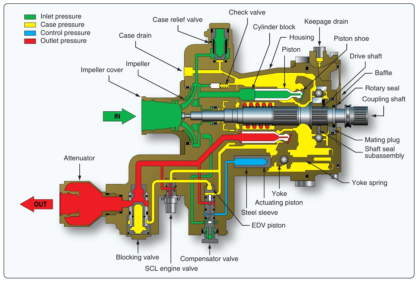
The fluid contained in the bore is precompressed, then expelled through the outlet port. Discharge pressure holds the piston shoe against the yoke bearing surface during the discharge stroke and also provides the shoe pressure balance and fluid film through an orifice in the piston and shoe subassembly.
With each revolution of the drive shaft and cylinder block, each piston goes through the pumping cycle described above, completing one intake and one discharge stroke. High-pressure fluid is ported out through the valve plate, past the blocking valve, to the pump outlet. The blocking valve is designed to remain open during normal pump operation. Internal leakage keeps the pump housing filled with fluid for lubrication of rotating parts and cooling. The leakage is returned to the system through a case drain port. The case valve relief valve protects the pump against excessive case pressure, relieving it to the pump inlet.
Normal Pumping Mode
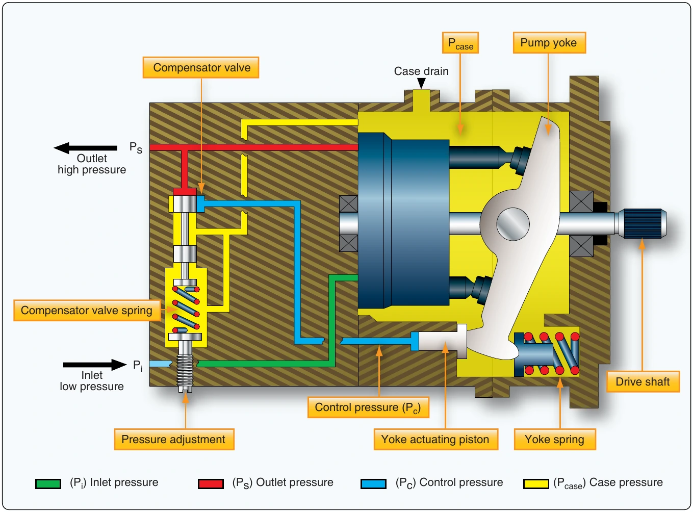
The pressure compensator is a spool valve that is held in the closed position by an adjustable spring load. [Figure 12-30] When pump outlet pressure (system pressure) exceeds the pressure setting (2,850 psi for full flow), the spool moves to admit fluid from the pump outlet against the yoke actuator piston. In Figure 12-30, the pressure compensator is shown at cracking pressure; the pump outlet pressure is just high enough to move the spool to begin admitting fluid to the actuator piston.
The yoke is supported inside the pump housing on two bearings. At pump outlet pressures below 2,850 psi, the yoke is held at its maximum angle relative to the drive shaft centerline by the force of the yoke return spring. Decreasing system flow demand causes outlet pressure to become high enough to crack the compensator valve open and admit fluid to the actuator piston.
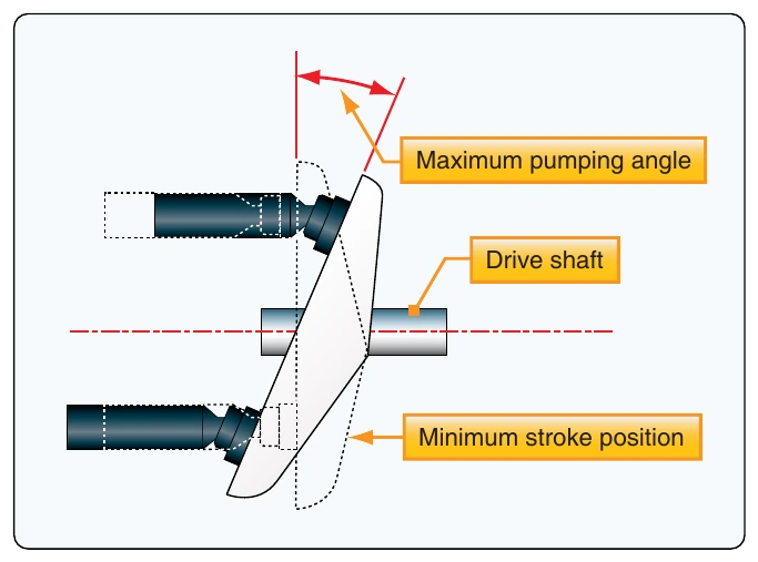
This control pressure overcomes the yoke return spring force and strokes the pump yoke to a reduced angle. The reduced angle of the yoke results in a shorter stroke for the pistons and reduced displacement. [Figure 12-31]
The lower displacement results in a corresponding reduction in pump flow. The pump delivers only that flow required to maintain the desired pressure in the system. When there is no demand for flow from the system, the yoke angle decreases to nearly zero degrees stroke angle. In this mode, the unit pumps only its own internal leakage. Thus, at pump outlet pressures above 2,850 psi, pump displacement decreases as outlet pressure rises. At system pressures below this level, no fluid is admitted through the pressure compensator valve to the actuator piston and the pump remains at full displacement, delivering full flow. Pressure is then determined by the system demand. The unit maintains zero flow at system pressure of 3,025 psi.
Depressurized Mode
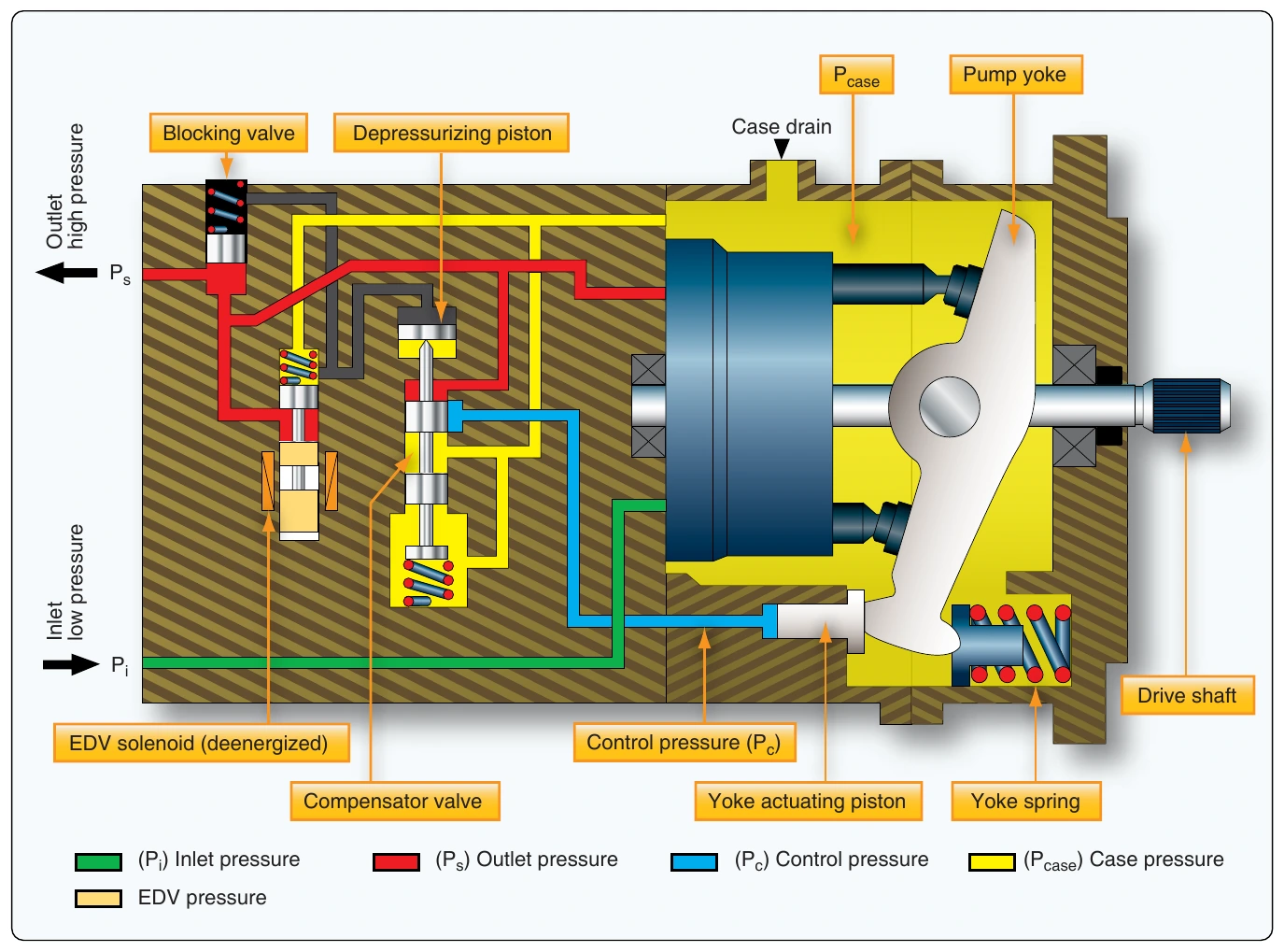
When the solenoid valve is energized, the electrical depressurization valve (EDV) solenoid valve moves up against the spring force and the outlet fluid is ported to the EDV control piston on the top of the compensator (depressurizing piston). [Figure 12-32] The high-pressure fluid pushes the compensator spool beyond its normal metering position. This removes the compensator valve from the circuit and connects the actuator piston directly to the pump outlet. Outlet fluid is also ported to the blocking valve spring chamber, which equalizes pressure on both sides of its plunger. The blocking valve closes due to the force of the blocking valve spring and isolates the pump from the external hydraulic system. The pump strokes itself to zero delivery at an outlet pressure that is equal to the pressure required on the actuator piston to reduce the yoke angle to nearly zero, approximately 1,100 psi. This depressurization and blocking feature can be used to reduce the load on the engine during startup and, in a multiple pump system, to isolate one pump at a time and check for proper system pressure output.
Valves
Flow Control Valves
Flow control valves control the speed and/or direction of fluid flow in the hydraulic system. They provide for the operation of various components when desired and the speed at which the component operates. Examples of flow control valves include: selector valves, check valves, sequence valves, priority valves, shuttle valves, quick disconnect valves, and hydraulic fuses.
Selector Valves
A selector valve is used to control the direction of movement of a hydraulic actuating cylinder or similar device. It provides for the simultaneous flow of hydraulic fluid both into and out of the unit. Hydraulic system pressure can be routed with the selector valve to operate the unit in either direction and a corresponding return path for the fluid to the reservoir is provided. There are two main types of selector valves: open-center and closed-center. An open center valve allows a continuous flow of system hydraulic fluid through the valve even when the selector is not in a position to actuate a unit. A closed-center selector valve blocks the flow of fluid through the valve when it is in the NEUTRAL or OFF position. [Figure 12-33A]
Selector valves may be poppet-type, spool-type, piston-type, rotary-type, or plug-type. [Figure 12-34] Regardless, each selector valve has a unique number of ports. The number of ports is determined by the particular requirements of the system in which the valve is used. Closed-centered selector valves with four ports are most common in aircraft hydraulic systems. These are known as four-way valves. Figure 12-33 illustrates how this valve connects to the pressure and return lines of the hydraulic system, as well as to the two ports on a common actuator. Most selector valves are mechanically controlled by a lever or electrically controlled by solenoid or servo. [Figure 12-35]