Chapter 12
Hydraulic & Pneumatic Power Systems
The hydraulic hand pump is used in some older aircraft for the operation of hydraulic subsystems and in a few newer aircraft systems as a backup unit. Hand pumps are generally installed for testing purposes, as well as for use in emergencies. Hand pumps are also installed to service the reservoirs from a single refilling station. The single refilling station reduces the chances for the introduction of fluid contamination.
Several types of hand pumps are used: single action, double action, and rotary. A single action hand pump draws fluid into the pump on one stroke and pumps that fluid out on the next stroke. It is rarely used in aircraft due to this inefficiency.
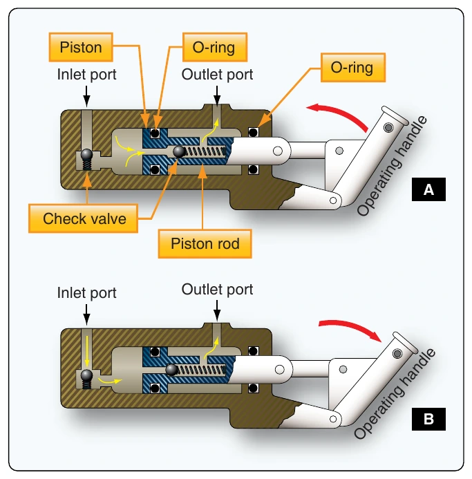
Double-action hand pumps produce fluid flow and pressure on each stroke of the handle. [Figure 12-19] The double-action hand pump consists essentially of a housing that has a cylinder bore and two ports, a piston, two spring-loaded check valves, and an operating handle. An O-ring on the piston seals against leakage between the two chambers of the piston cylinder bore. An O-ring in a groove in the end of the pump housing seals against leakage between the piston rod and housing.
When the piston is moved to the right, the pressure in the chamber left of the piston is lowered. The inlet port ball check valve opens, and hydraulic fluid is drawn into the chamber. At the same time, the rightward movement of the piston forces the piston ball check valve against its seat. Fluid in the chamber to the right of the piston is forced out of the outlet port into the hydraulic system. When the piston is moved to the left, the inlet port ball check valve seats. Pressure in the chamber left of the piston rises, forcing the piston ball check valve off of its seat. Fluid flows from the left chamber through the piston to the right chamber. The volume in the chamber right of the piston is smaller than that of the left chamber due to the displacement created by the piston rod. As the fluid from the left chamber flows into the smaller right chamber, the excess volume of fluid is forced out of the outlet port to the hydraulic system.
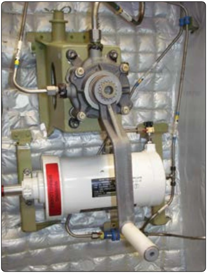
A rotary hand pump may also be employed. It produces continuous output while the handle is in motion. Figure 12-20 shows a rotary hand pump in a hydraulic system.
Power-Driven Pumps
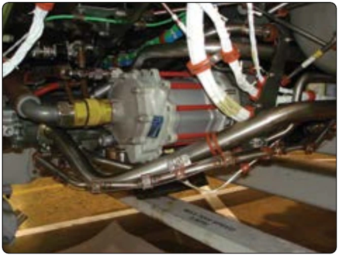
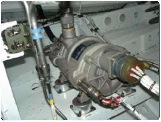
Many of the power driven hydraulic pumps of current aircraft are of variable delivery, compensator-controlled type. Constant delivery pumps are also in use. Principles of operation are the same for both types of pumps. Modern aircraft use a combination of engine-driven power pumps, electrical-driven power pumps, air-driven power pumps, power transfer units (PTU), and pumps driven by a RAT. For example, large aircraft, such as the Airbus A380, have two hydraulic systems, eight engine-driven pumps, and three electrical driven pumps. The Boeing 777 has three hydraulic systems with two engine driven pumps, four electrical driven pumps, two air driven pumps, and a hydraulic pump motor driven by the RAT. [Figure 12-21 and 12-22]
Classification of Pumps
All pumps may be classified as either positive-displacement (constant displacement) or nonpositive-displacement (variable displacement). Most pumps used in hydraulic systems are positive displacement. Engine driven pumps may be either constant displacement or variable displacement. A nonpositive-displacement pump produces a continuous flow. However, because it does not provide a positive internal seal against slippage, its output varies considerably as pressure varies. Centrifugal and impeller pumps are examples of nonpositive-displacement pumps. If the output port of a nonpositive-displacement pump was blocked off, the pressure would rise, and output would decrease to zero.
Although the pumping element would continue moving, flow would stop because of slippage inside the pump. In a positive-displacement pump, slippage is negligible compared to the pump’s volumetric output flow. If the output port were plugged, pressure would increase instantaneously to the point that the pump pressure relief valve opens.
Constant-Displacement Pumps
A constant-displacement pump, regardless of pump rotations per minute, forces a fixed or unvarying quantity of fluid through the outlet port during each revolution of the pump. Constant-displacement pumps are sometimes called constant-volume or constant-delivery pumps. They deliver a fixed quantity of fluid per revolution, regardless of the pressure demands. Since the constant-delivery pump provides a fixed quantity of fluid during each revolution of the pump, the quantity of fluid delivered per minute depends upon pump rotations per minute. When a constant-displacement pump is used in a hydraulic system in which the pressure must be kept at a constant value, a pressure regulator is required.
Gear-Type Power Pump
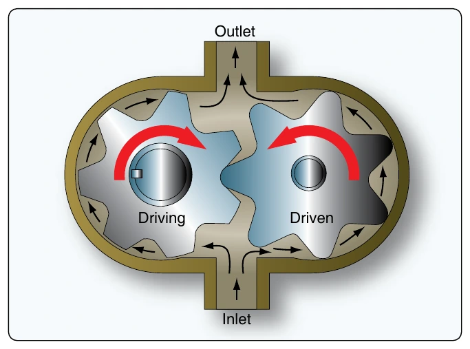
A gear-type power pump is a constant-displacement pump. It consists of two meshed gears that revolve in a housing. [Figure 12-23] The driving gear is driven by the aircraft engine or some other power unit. The driven gear meshes with, and is driven by, the driving gear. Clearance between the teeth as they mesh and between the teeth and the housing is very small. Excessive clearance will result in lower output pressure. The inlet port of the pump is connected to the reservoir, and the outlet port is connected to the pressure line.
When the driving gear turns, as shown in Figure 12-23, it turns the driven gear. Fluid is captured by the teeth as they pass the inlet, and it travels around the housing and exits at the outlet.