
Chapter 12
Hydraulic & Pneumatic Power Systems
- Aircraft airborne.
- No. 1 engine rpm drops below a limit value.
- Landing gear lever is up.
- Either or both main landing gear not up and locked.
Standby Hydraulic System
The standby hydraulic system is provided as a backup if system A and/or B pressure is lost. The standby system can be activated manually or automatically and uses a single electric ACMP to power:
- Thrust reversers.
- Rudder.
- Leading edge flaps and slats (extend only).
- Standby yaw damper.
Indications
A master caution light illuminates if an overheat or low pressure is detected in the hydraulic system. An overheat light on the flight deck illuminates if an overheat is detected in either system A or B and a low-pressure light illuminates if a low pressure is detected in system A and B.
Boeing 777 Hydraulic System
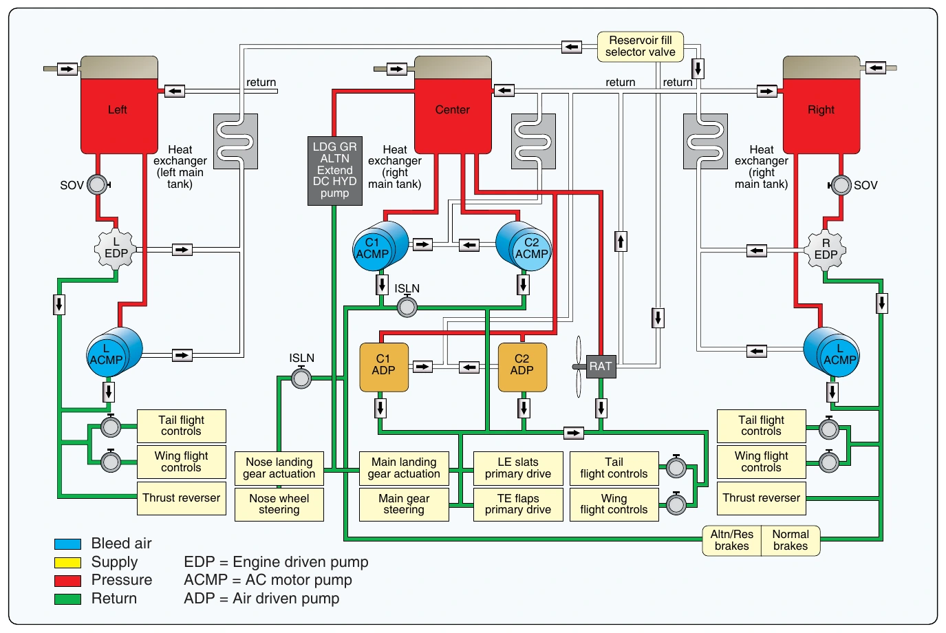
The Boeing 777 is equipped with three hydraulic systems. The left, center, and right systems deliver hydraulic fluid at a rated pressure of 3,000 psi (207 bar) to operate flight controls, flap systems, actuators, landing gear, and brakes. Primary hydraulic power for the left and right systems is provided by two EDPs and supplemented by two on-demand ACMPs. Primary hydraulic power for the center system is provided by two electric motor pumps (ACMP) and supplemented by two on-demand air turbine-driven pumps. The center system provides hydraulic power for the engine thrust reversers, primary flight controls, landing gear, and flaps/slats. Under emergency conditions, hydraulic power is generated by the ram air turbine (RAT), which is deployed automatically and drives a variable displacement inline pump. The RAT pump provides flow to the center system flight controls. [Figure 12-66]
Left & Right System Description
The left and right hydraulic systems are functionally the same. The left hydraulic system supplies pressurized hydraulic fluid to operate the left thrust reverser and the flight control systems. The right hydraulic system supplies pressurized hydraulic fluid to operate the right thrust reverser, flight control systems, and the normal brake system. [Figure 12-67]
Reservoir
The hydraulic system reservoirs of the left and right system contain the hydraulic fluid supply for the hydraulic pumps. The reservoir is pressurized by bleed air through a reservoir pressurization module. The EDP draws fluid through a standpipe. The ACMP draws fluid from the bottom of the reservoir. If the fluid level in the reservoir gets below the standpipe, the EDP cannot draw any fluid any longer, and the ACMP is the only source of hydraulic power. The reservoir can be serviced through a center servicing point in the fuselage of the aircraft. The reservoir has a sample valve for contamination testing purposes, a temperature transmitter for temperature indication on the flight deck, a pressure transducer for reservoir pressure, and a drain valve for reservoir draining.
Pumps
The EDPs are the primary pumps for the left and right hydraulic systems. The EDPs get reservoir fluid through the EDP supply shutoff valves. The EDPs operates whenever the engines operate. A solenoid valve in each EDP controls the pressurization and depressurization of the pump. The pumps are variable displacement inline piston pumps consisting of a first stage impeller pump and a second stage piston pump. The impeller pump delivers fluid under pressure to the piston pump. The ACMPs are the demand pumps for the left and right hydraulic systems. The ACMPs normally operate only when there is high hydraulic system demand.
Filter Module
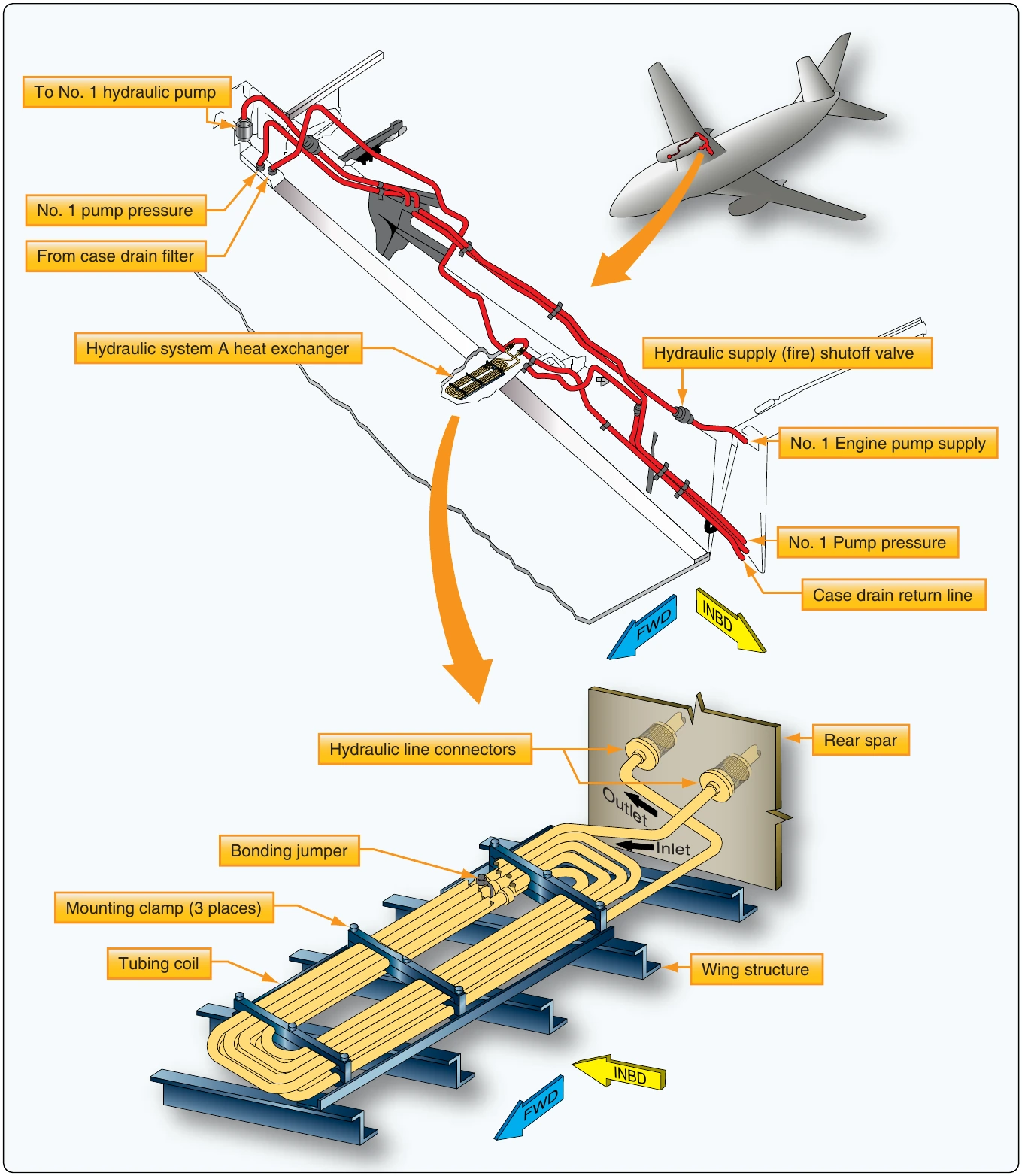
Pressure and case drain filter modules clean the pressure flows and the case drain flows of the hydraulic pumps. A return filter module cleans the return flow of hydraulic fluid from the user systems. The module can be bypassed if the filter clogs, and a visible indicator pops to indicate a clogged filter. The heat exchanger, which is installed in the wing fuel tanks, cools the hydraulic fluid from ACMP and EDP case drain lines before the fluid goes back to the reservoir.