Chapter 12
Hydraulic & Pneumatic Power Systems
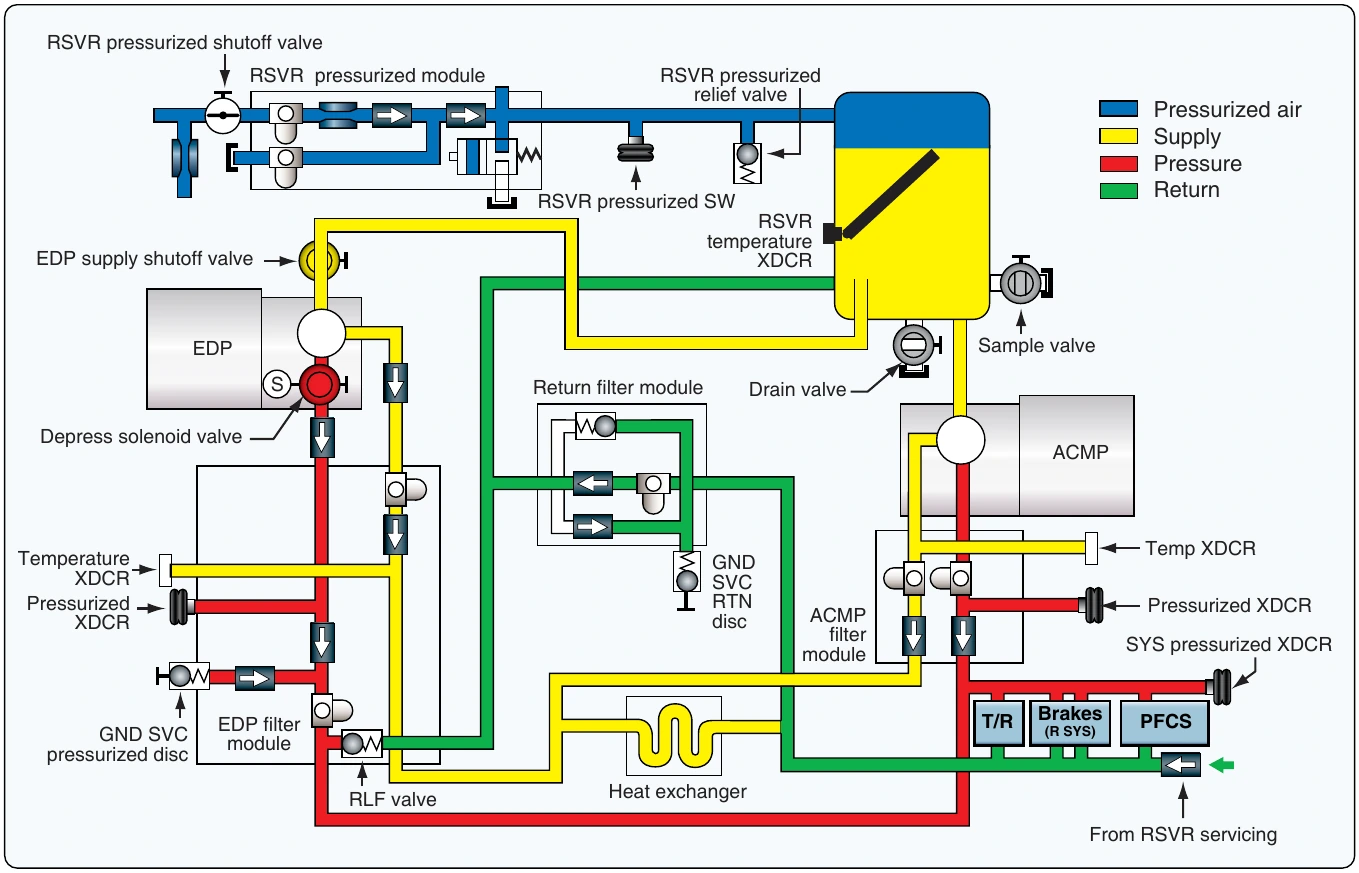
The hydraulic system sensors send pressure, temperature, and quantity signals to the flight deck. A reservoir quantity transmitter and temperature transducer are installed on each of the reservoirs, and a hydraulic reservoir pressure switch is located on the pneumatic line between the reservoir pressurization module and the reservoir. The ACMP and EDP filter modules each have a pressure transducer to measure pump output pressure. A temperature transducer is installed in the case drain line of each filter module and measures pump case drain fluid temperature. A system pressure transducer measures hydraulic system pressure. A pressure relief valve on the EDP filter module protects the system against overpressurization. [Figure 12-67]
Center Hydraulic System
The center hydraulic system supplies pressurized hydraulic fluid to operate these systems. [Figure 12-68]
- Nose landing gear actuation.
- Nose landing gear steering.
- Alternate brakes.
- Main landing gear actuation.
- Main landing gear steering.
- Trailing edge flaps.
- Leading edge slat.
- Flight controls.
Reservoir
The hydraulic system reservoir of the center system contains the hydraulic fluid supply for the hydraulic pumps. The reservoir is pressurized by bleed air through a reservoir pressurization module. The reservoir supplies fluid to the ADPs, the RAT, and one of the ACMPs through a standpipe. The other ACMP gets fluid from the bottom of the reservoir. The reservoir also supplies hydraulic fluid to the landing gear alternate extension system.
The ACMPs are the primary pumps in the center hydraulic system and are normally turned on. The ADPs are the demand pumps in the center system. They normally operate only when the center system needs more hydraulic flow capacity. The RAT system supplies an emergency source of hydraulic power to the center hydraulic system flight controls. A reservoir quantity transmitter and temperature transducer are installed on the reservoir. A hydraulic reservoir pressure switch is installed on the pneumatic line between the reservoir and the reservoir pressurization module.
Filter
Filter modules clean the pressure and case drain output of the hydraulic pumps. A return filter module cleans the return flow of hydraulic fluid from the user systems. The module can be bypassed. The heat exchanger cools the hydraulic fluid from the ACMP case drains before the fluid goes back to the reservoir. ADP case drain fluid does not go through the heat exchangers.
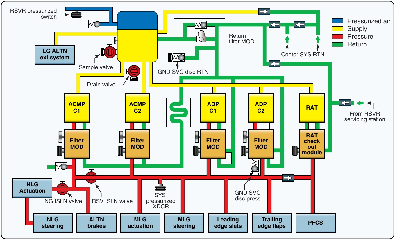
The ACMP and ADP filter modules each have a pressure transducer to measure pump output pressure. A temperature transducer in each filter module measures the pump case drain temperature. A system pressure transducer measures hydraulic system pressure.
Pressure relief valves in each ADP filter module prevent system overpressurization. A pressure relief valve near ACMP C1 supplies overpressure protection for the center hydraulic isolation system (CHIS).
Center Hydraulic Isolation System (CHIS)
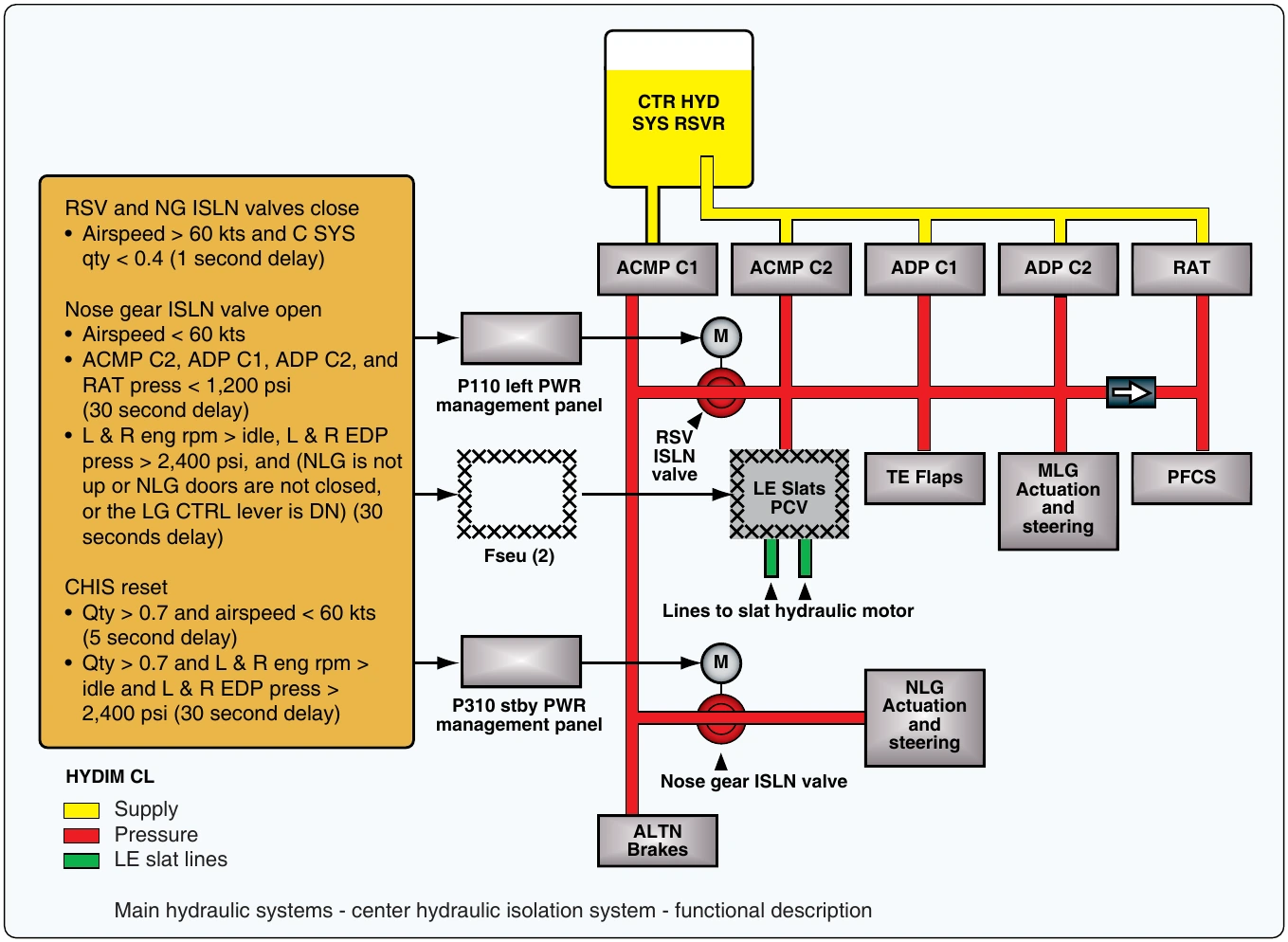
The CHIS supplies engine burst protection and a reserve brakes and steering function. CHIS operation is fully automatic. Relays control the electric motors in the reserve and nose gear isolation valves. When the CHIS system is operational, it prevents hydraulic operation of the leading-edge slats.
ACMP C1 gets hydraulic fluid from the bottom of the center system reservoir. All other hydraulic pumps in the center system get fluid through a standpipe in the reservoir. This gives ACMP C1 a 1.2-gallon (4.5 liter) reserve supply of hydraulic fluid.
The reserve and nose gear isolation valves are normally open. Both valves close if the quantity in the center system reservoir is low (less than 0.40) and the airspeed is more than 60 knots for more than one second. When CHIS is active, this divides the center hydraulic system into different parts. The NLG actuation and steering and the leading-edge slat hydraulic lines are isolated from center system pressure. The output of ACMP C1 goes only to the alternate brake system.
The output of the other center hydraulic system pumps goes to the trailing edge flaps, the MLG actuation and steering, and the flight controls. If there is a leak in the NLG actuation and steering or LE slat lines, there is no further loss of hydraulic fluid. The alternate brakes, the trailing edge flaps, the MLG actuation and steering, and the PFCS continue to operate normally.
If there is a leak in the trailing edge flaps, the MLG actuation and steering, or the flight control lines, the reservoir loses fluid down to the standpipe level (0.00 indication). This causes a loss of these systems, but the alternate brake system continues to get hydraulic power from ACMP C1. If there is a leak in the lines between ACMP C1 and the alternate brake system, all center hydraulic system fluid is lost.