
Chapter 12
Hydraulic & Pneumatic Power Systems
Control Valves
Control valves are also a necessary part of a typical pneumatic system. Figure 12-72 illustrates how a valve is used to control emergency air brakes. The control valve consists of a three-port housing, two poppet valves, and a control lever with two lobes.
In Figure 12-72A, the control valve is shown in the off position. A spring holds the left poppet closed so that compressed air entering the pressure port cannot flow to the brakes. In Figure 12-72B, the control valve has been placed in the on position. One lobe of the lever holds the left poppet open, and a spring closes the right poppet. Compressed air now flows around the opened left poppet, through a drilled passage, and into a chamber below the right poppet. Since the right poppet is closed, the high-pressure air flows out of the brake port and into the brake line to apply the brakes.
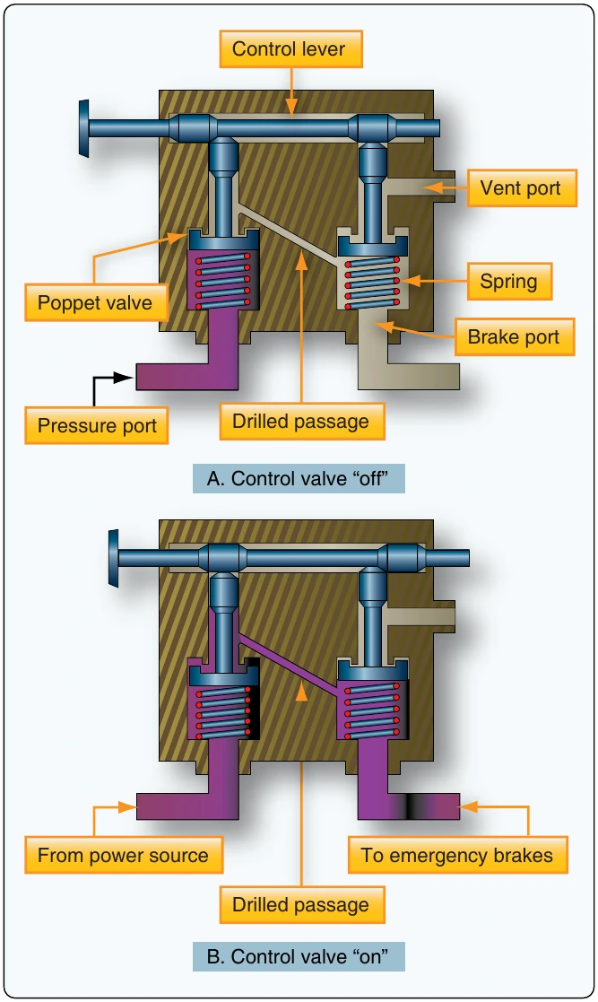
To release the brakes, the control valve is returned to the off position. [Figure 12-72A] The left poppet now closes, stopping the flow of high-pressure air to the brakes. At the same time, the right poppet is opened, allowing compressed air in the brake line to exhaust through the vent port and into the atmosphere.
Check Valves
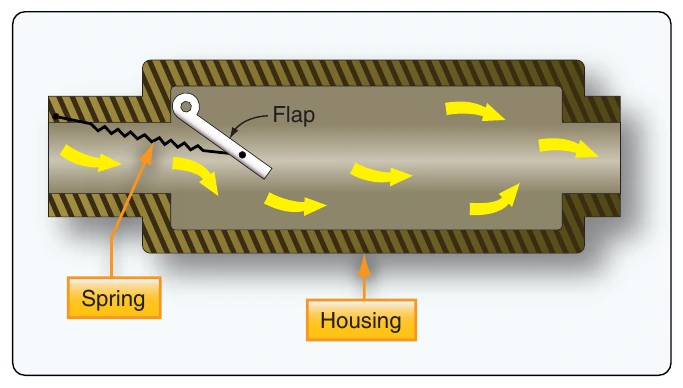
Check valves are used in both hydraulic and pneumatic systems. Figure 12-73 illustrates a flap-type pneumatic check valve. Air enters the left port of the check valve, compresses a light spring, forcing the check valve open and allowing air to flow out of the right port. But if air enters from the right, air pressure closes the valve, preventing a flow of air out of the left port. Thus, a pneumatic check valve is a one-direction flow control valve.
Restrictors
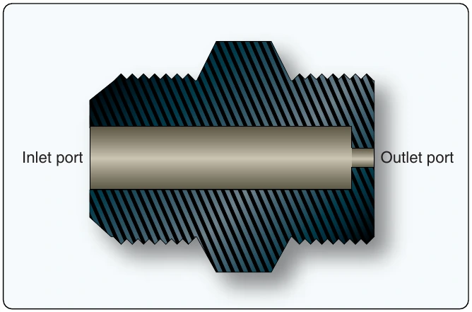
Restrictors are a type of control valve used in pneumatic systems. Figure 12-74 illustrates an orifice-type restrictor with a large inlet port and a small outlet port. The small outlet port reduces the rate of airflow and the speed of operation of an actuating unit.
Variable Restrictor
Another type of speed-regulating unit is the variable restrictor. [Figure 12-75] It contains an adjustable needle valve, which has threads around the top and a point on the lower end. Depending on the direction turned, the needle valve moves the sharp point either into or out of a small opening to decrease or increase the size of the opening. Since air entering the inlet port must pass through this opening before reaching the outlet port, this adjustment also determines the rate of airflow through the restrictor.
Filters
Pneumatic systems are protected against dirt by means of various types of filters. A micronic filter consists of a housing with two ports, a replaceable cartridge, and a relief valve. Normally, air enters the inlet, circulates around the cellulose cartridge, and flows to the center of the cartridge and out the outlet port. If the cartridge becomes clogged with dirt, pressure forces the relief valve open and allows unfiltered air to flow out the outlet port.
A screen-type filter is similar to the micron filter but contains a permanent wire screen instead of a replaceable cartridge. In the screen filter, a handle extends through the top of the housing and can be used to clean the screen by rotating it against metal scrapers.
Desiccant/Moisture Separator
The moisture separator in a pneumatic system is always located downstream of the compressor. Its purpose is to remove any moisture caused by the compressor. A complete moisture separator consists of a reservoir, a pressure switch, a dump valve, and a check valve. It may also include a regulator and a relief valve. The dump valve is energized and deenergized by the pressure switch. When deenergized, it completely purges the separator reservoir and lines up to the compressor. The check valve protects the system against pressure loss during the dumping cycle and prevents reverse flow through the separator.
Chemical Drier
Chemical driers are incorporated at various locations in a pneumatic system. Their purpose is to absorb any moisture that may collect in the lines and other parts of the system. Each drier contains a cartridge that should be blue in color. If otherwise noted, the cartridge is to be considered contaminated with moisture and should be replaced.